Martin's Blog

Electronics, embedded firmware and software development from the perspective of 30 years in the industry.

Unit Testing Embedded C: On-Target with minunit and Off-Target with MS Test

Generally, the advice on unit testing in embedded environments is to run your tests on the PC host rather than on the target device. Whilst I agree that this is the most productive arrangement, there are a variety of reasons for needing to test on the target which can be convincing in certain situation. The technique described here allows for both. Mike Long in his GOTO 2015 presentation Continuous Delivery for Embedded Systems says "Test on your host because that's fast - it's a really fast way to develop. But also test on the target because behaviour can change in different ways, different compilers, different hardware..." Niall Cooling in his talk at the EmbeddedOnlineConference 2020 "How agile is changing the face of embedded software development" says (at 46m) on the gap between testing on the host and the target Things like TDD really are based on testing in the host, and really that's fine but of course we are typically using host compilers like host GCC and of course we know that at the moment this is typically going to be an Intel based processor. So we are compiling for the underlying OS. And it is good for finding a…

Continue reading...
Answering My Own Interview Question On Integer Maths In C

I've been using this interview question for the last 20 years to test embedded C engineers: Given the formula for Fahrenheit as 9 * C + 32 = F - 5 Write a function to convert unsigned char tempInC to unsigned char tempInF (ie. All values are bytes, including intermediate results). The processor has no floating point library.Recently I was intrigued to find that a very similar problem was posed by professor James M. Conrad at the University of North Carolina at Charlotte at this point in his lecture on Embedded Systems: Software Testing. The responses I used to get were similar to what the students gave in that video. Whilst some candidates would think this was a maths problem that needed rearranging to solve for tempInC, others thought that I just wanted them to write the formula in C syntax. A large percentage of candidates would ignore the premise of the question and cast the parameters to floats, do the calculation as a floating point one and cast the result back to integers. As well as being not anywhere near what I was asking for, this approach leads to rounding down so that 21°C, which should be converted to…

Continue reading...

Using and Misusing CRCs

CRCs are used for error detection in communication systems and storage systems. They have a combination of several advantageous properties whilst only requiring a short FCS, but they do have their limitations. If you require error correction as well as detection then you have to look at a different class of algorithms and will have to add much more redundancy to the codeword. The rest of this post is about message systems, where if an error is detected, the link layer of the protocol will take various actions such as discarding the message, sending a NACK, requesting a retry, waiting for retry until a timeout occurs etc. Another use of CRCs is for protecting data in memory, where similar considerations apply but the corruption possibilities may be different so you have to consider if the single random bit-flips model is still appropriate. If you just need to protect a single 8, 16 or 32 bit value, choose from this list and use a non-zero seed. Unless your protocol design is such that the messages are fixed length, one of the fields in the message will be the message length or an equivalent which points to the position of the FCS.

Continue reading...

Choosing an Optimal CRC Polynomial

Most of the time engineers just have to implement communications protocols that are given to them: industry standards, decided by committees or established by the dominant players. But surprisingly often there is the opportunity to create a new protocol, either for proprietary internal use or as part of inventing a new standard for the industry, and in those cases we have to choose a CRC polynomial. Although the process sounds complicated, in many cases it can be quite simple. But first we must make sure we don't fall into one of the common pitfalls which leads to sub-optimal performance. Be wary of the many excuses for using a standard CRC Before you go ahead with a standard polynomial know that it is not the only choice and may well not be the best choice. What you are doing by choosing a standard one is saying don't blame me, everyone uses this. As it says on mathpages.com if you use a standard polynomial and subsequently it turns out to be particularly unsuitable for your circumstances, "This would be incredibly bad luck, but if it ever happened, you'd like to at least be able to say you were using an industry standard…

Continue reading...

You Are Probably Using A Sub-Optimal CRC

The designers of serial protocols like USB, Ethernet, CAN, or anything using "CRC-8" or "CRC-16 CCITT" did not have access to information on which CRC polynomials are the best for their bit-size and application, so were chosen on what seemed to be reasonable grounds but are now known to be sub-optimal. It is not necessarily that better polynomials were unknown in academic research but that the information had not reached an industrial design audience. In fact, it was widely believed that the performance of the polynomials was similar enough that you could just randomly pick one from a list in a book and it would be fine for your application. Koopman said CRCs have been around for a really long time. You would think that after all these years, the best CRC is a well solved problem. Unfortunately, it isn't really.... Until fairly recently, the compute power wasn't available to do an exhaustive search. ... The other problem is that the literature is poorly accessible to computer engineers, a lot of it is written in dense math that's hard to apply ... So as a result, practitioners mostly use what someone else used and they assume it's good and that…

Continue reading...

Clearing Up CRC Terminology and Representations of Polynomials

In the first post of this series on CRCs, I'm just going to clarify the terminology used. I am not going to cover the maths of how CRCs work in these posts, which can get surprisingly complex for what appears to be a set of simple bitwise manipulations and instead defer to Ben Eater's excellent CRC tutorial on YouTube. Small correction to the video, as noticed by commenter David W Smith, the length shown in Prof. Koopman's tables are in bits not bytes. They are for the dataword i.e. not including the FCS. I'm going to follow Prof. Koopman in his terminology Code Word is the whole message, with the payload being the dataword. Note that in this definition, any header is included in the Data Word. The Frame Check Sequence is the addition to the payload which adds redundancy and hence allows errors to be detected. It is an error code of a type given in Error Coding. The FCS must be after the data word to get the burst error detection benefits. Hamming distance (HD) is how many bits have to be changed to get from one valid codeword to another, as a minimum. This means that all…

Continue reading...

Hitting the Precision Limit of Excel; or 15 Digits Should be Enough for Everyone

Excel is a great all purpose tool, used by maybe 7% of the world's population. From shopping lists to budgets, Gantt charts and calendars to circuit simulators and digital music workstations, it can do it all. It is so good at so many things and so universally available to businesses that in many cases the biggest competition for software startups is not other specialized software solving the same problems but Excel. When it comes to using Excel for engineering tasks, there are lots of known pitfalls. Treating values as dates, or strings which are supposed to be hex like "51E67" as scientific format is one big category of pitfalls. Another is that although the probability of an error in any one cell is small, when you have a high number of cells all dependent on each other, the probability of error somewhere in the sheet means that the final result is likely to be wrong. The canonical case study is Reinhart and Rogoff, covered by a talk I highly recommend, Emery Berger's "Saving the World from Spreadsheets". So cross checking or auditing become necessary. Use CTRL-` to switch between formula view and value view. In common with many computer languages,…

Continue reading...

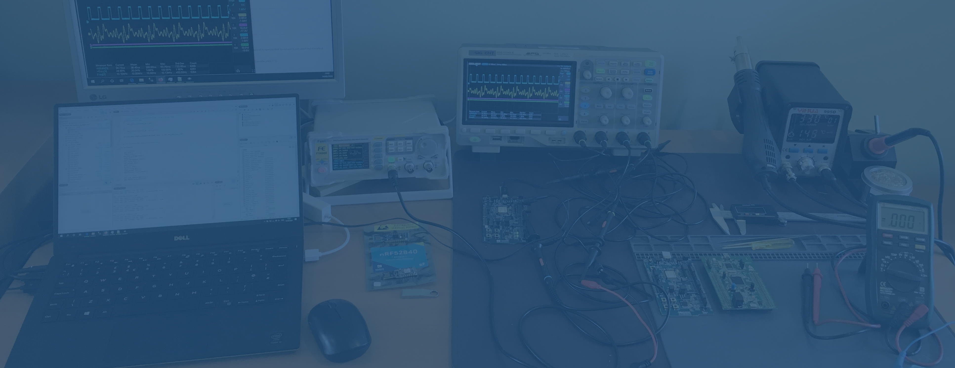
My All-Digital Instruments Electronics Lab

I've been building up this set of equipment on my bench at home over the last few months, with some older kit reused. It's the minimum needed to do embedded development and I don't even have a bench power supply yet. I can get away without one since the dev kits are USB powered, but when I need one I have my eye on the Gophert NPS-1601 From top left to bottom right 1280 x 1024 @ 60 Hz VGA and DVI inputs, USB hub with 2 downstream USB-A. Was £360 in 2003. 13" 1920 x 1080 @ 60 Hz matte non-touch display Intel i5-5200 CPU @ 2.20GHz (Broadwell-U, 14nm, 2 cores, 4 threads) 8 GB DDR3 RAM, 256 GB SSD Liteon L8H-256V2G-11M.2 Intel HD Graphics 5500 Windows 10 Home USB3 Type A x2, Mini Display Port, 3.5mm phones/mic, SD Card slot Liteon disk results in AS SSD Benchmark 1.7 Read: Seq @ 514 MB/s, 4k @ 22 MB/s, Acc Time 0.12ms Write: Seq @ 225 MB/s, 4k @ 57 MB/s, Acc Time 0.08ms Review Reference Guide Full HD 1080p on DVI & VGA, 4k on HDMI Buy (Amazon) was £17 in 2021. Buy (Amazon) was £8 in 2016. 14…

Continue reading...

Porting NovelBits' BLE Central Lightbulb controller to nRF51 & SDK version 12

Having got the BLE Lightbulb peripheral example working as I wanted it to on the nRF52 development kit (PCA10040), the next step was to get my other dev kit to be the controller for it, in place of the smartphone app. NovelBits helpfully provides all the code for this on the page How to build the simplest nRF52 BLE Central (Lightbulb use case) but it is targeted at the nRF52840 and SDK 15. I only had one nRF52 dev kit and one nRF51 dev kit. As I learned previously, the nRF51 is only supported by SDK version 12, so I had the job of porting the example code down from SDK version 15 and changing it over to the smaller, M0 based chip. At the same time, the Softdevice (BTLE stack) changes from s132 to s130. My plan was to proceed cautiously, having seen the problems previously in attempting to make many changes in one step and ending up with an uncompilable codebase. As soon as you copy the project folder into the same location in the SDK 12 folder and run my SES Include File Manager, you see that of the 133 include paths 29 are not found,…

Continue reading...

An Include File Manager for Segger Embedded Studio with Nordic SDK

SES Include File ManagerA simple helper application for use with Segger Embedded Studio when working with the Nordic Semiconductor SDK. The application checks which paths exist and allows you to remove those that don’t, allows a search by filename to show which folder they are in, and allows conversion between relative and absolute paths for the include folders. (It does not search your SDK folder for include files to automatically add them to the include paths.) The Nordic SDK folder is structured so that many include files which are needed for a project are in different folders. All of the folder paths need to be added to the c_user_include_directories definition for the project to compile. It is time consuming to search for each include file that a compile will complain about being missing so that it’s path can be added to the project c_user_include_directories. It is easy to end up with duplicate paths and unnecessary paths. The relative path can be tricky to manage due to its change of depth (number of ../) when a project is moved within the folder structure. Opens the file, parses it and shows the results in two lists - Include Paths and Include Files.

Continue reading...

Attempting to read and write emProject files as XML

Segger Embedded Studio project files appear to be XML formatted with a custom DOCTYPE. <!DOCTYPE CrossStudio_Project_File> <solution Name="ble_app_MA_lightbulb_pca10040_s132" target="8" version="2"> <project Name="ble_app_MA_lightbulb_pca10040_s132"> <configuration Name="Common" arm_architecture="v7EM" arm_core_type="Cortex-M4" arm_endian="Little" arm_fp_abi="Hard" arm_fpu_type="FPv4-SP-D16" arm_linker_heap_size="8192" arm_linker_process_stack_size="0" arm_linker_stack_size="8192" arm_linker_treat_warnings_as_errors="No" ... /> <configuration Name="Debug" c_preprocessor_definitions="DEBUG; DEBUG_NRF" gcc_optimization_level="None" /> </solution>ReadingIn VB.NET, Private xmlDoc As XmlDocument = New XmlDocument()xmlDoc.PreserveWhitespace = TruexmlDoc.XmlResolver = NothingxmlDoc.Load(filename)Once the XML is loaded, an attribute such as c_user_include_directories can be read using this syntax sIncludes = xmlDoc.SelectSingleNode("solution/project/configuration[@c_user_include_directories]").Attributes("c_user_include_directories").ValueWritingHowever, writing out an this XML document object back to a file has a few problems. The DOCTYPE tag changes in that additional square brackets [] appear at the end due to a bug in the .NET framework, so you get <!DOCTYPE CrossStudio_Project_File []> which although is valid XML, causes SES to say that the file is not a valid project. The workaround is to create a new XML Document object and replace the Document Type with a new one, with Nothing (in VB.NET, equivalent to null in C#) for the subset object, as distinct from an empty string. Dim n As XmlDocument = New XmlDocument()n = xmlDoc.Clone()Dim parent As XmlNode = n.DocumentType.ParentNode'4th param in CreateDocumentType has to be Nothing to avoid getting [] in DOCTYPE, which is what…

Continue reading...

Adding Brightness Control to the BLE Lightbulb Example

In the previous post on using a BLE peripheral example, the LED2 could only be controlled in terms of two states, On and Off. With my background of lighting controls, I wasn't satisfied that this could be called a BLE lightbulb project without at least brightness control. Since the example BLE code is already set up to send a byte as the BLE characteristic value, it should be easy to expand the example to brightness control in percentage terms using the byte in the range 0 to 100. The main addition to the previous project is the PWM software module which sets up and controls the internal PWM hardware peripheral on the nRF52832. It is better to use an existing software module which encodes all the knowledge necessary to set up the PWM peripheral rather than just accessing the registers directly which would mean careful study of the datasheet with possible misinterpretation and that gives us an interface layer for future portability. The first location I tried looking for a reference example was SDK\examples\peripheral\led_softblink but it was not suitable for a couple of reasons. led_softblink uses a low power technique for the PWM which involves setting up the PWM timer and…

Continue reading...

UUID Generator for Bluetooth Low Energy Products

If you are developing a BLE application with Nordic Semi's SDK, there is a need to generate a UUID for your custom services and characteristics, for example, NovelBits MIDI example. Mohammad Afaneh gives the rules for these UUIDs and suggests using a general purpose UUID generator followed by a manual check for clashes with the BT SIG reserved range. The Nordic SDK method of declaring these UUIDs requires them to be given as byte arrays in reverse order, with least significant byte first. Although this is not difficult to do manually, there is some possibility of error which would be difficult to detect without going through the full debug cycle of programming a device and reading back the UUIDs on a tool such as LightBlue or nRF Connect. I have automated the whole process in a simple Windows Form app - BLE UUID Generator The program generates a UUID immediately when opened, using the built-in Windows GUID functionality. This is checked for collision with the BT SIG reserved range XXXXXXXX-0000-1000-8000-00805F9B34FB and then displayed in the text box as a snippet of C code - as a comment and as a reversed order byte array as required by the Nordic SDK. It…

Continue reading...

Getting a Simple On/Off BLE Peripheral Example To Work

I was getting a little frustrated with the Nordic examples and tutorials all being not quite ready for use. Not as badly frustrated as this guy but there always seemed to be some mismatch between what was required and what I was using, even when I chose the preferred tools. OK, I made a mistake assuming that I should start with the nRF51-DK because that is a smaller, simpler, cheaper chip. Although when you look into pricing, you find that nRF51's are not necessarily cheaper So I got myself onto the nRF52-DK so that I could use the latest SDK 16 and the Segger SES toolchain, which meets all the requirements in the Getting Starting guide. After going through that, I wanted to find a tutorial that was written from outside Nordic Semi so that it could be more objective about the tools. Given that Mohammad Afaneh is presenting these Ellisys BT videos he seems to be an independent (of Nordic) expert, so his post on How to build the simplest nRF52 BLE Peripheral application (Lightbulb use case) seemed to be a good fit with what I wanted to learn and how to learn it. The rest of this post is my attempt to…

Continue reading...

Comparison of 4.7" iPhones

Apple have just announced their latest 4.7" iPhone. Confusingly they are calling it the iPhone SE, even though they already had an iPhone SE which was a 4" screen. I'm looking at it as an upgrade to the iPhone 6s 128 GB from September 2015, so the comparison only covers that screen size. Most of the data in this chart is from Apple's comparison page. CPU and battery specs are from the relevant Wikipedia pages. The historical UK pricing at launch was obtained from the Guardian. DXO Mark and Geekbench scores are from their own sites. Bold text is used for improvements. Since the iPhone 8 did not launch with a 128 GB option, the choice would have been the 256 GB option at £849 so the iPhone SE (2nd gen) at 128GB at £469 looks like a good deal. Added confirmed DXOMark, RAM and CPU for SE (2nd). Added iPhone 12 mini

Continue reading...

Eliminate Useless Timer Interrupts by Coalescing Timers

While learning about RTOSes, I came across the idea of Timer Coalescing which improves performance by eliminating unnecessary context switches. But there is no reason that this technique cannot be applied to bare metal firmware (without RTOS). To test out how well it works, I implemented it using a STM32F4 discovery board. I wanted to see the improvement factor in a typical use case, so I decided on running 8 software timers on a 1ms timer peripheral. The software timers count down to 0 then reload themselves. From previous experience, typical periods were chosen for these timers of 1000, 200, 125, 50, 18, 27, 40 and 600ms. (If they had a common factor of say 5ms, then it would make more sense to use that as the peripheral timer rate, but it restricts the flexibility for future changes.) TIM6 was chosen because we only need a Basic 16 bit timer in the STM32F4 architecture. It runs off APB1 at 42 MHz (HCLK at 168 MHz). Prescaler was set to 41, Counter Period ARR set to 1999 for 1ms and auto-reload preload set to Disable. TIM6 interrupts were enabled. Once all this is set up in the Device Configuration Tool, all…

Continue reading...

How your Obeng Project Type affects your Planning, Methodology and Leadership

Knowing what kind of project you are working on can help you work out which planning method and software methodology to apply, as well as what management strategy to use. Once you have categorised your project into one of these four types, you will improve your expectations about the timescale and velocity. Not knowing about these project types leads to confusion about the project direction and pace, which can be demoralising for staff and leads to misunderstanding by customers, management and other departments. The trend in the last 20 years has been to apply Agile methodologies to all projects, but this Feabhas video explains why that isn't always a good idea. (The click-baity title isn't what it first appears). I'd like to expand on the video by looking at the relationship between these four project types and the appropriate planning and execution strategies. These four project types were described by Eddie Obeng, who said "As a project manager, as a business, we have to understand the type of project that we are working on because each type of project has a different management strategy associated with it. More specifically, we have to apply our effort in different places and in different ways…

Continue reading...

Trying to use nRF5 SDK 12.3.0 for nRF51 on a FreeRTOS project

Continuing from my Getting Started post, we now want to use the same method on a FreeRTOS example such as ble_app_hrs_freertos. When compiling, we get file include path problems, starting with nrf_ble_gatt.h. These can be fixed by adding the following entries into the Project - Options - Preprocessor - User Include Directories ../../../../../../components/ble/nrf_ble_gatt../../../../../../components/libraries/sensorsim../../../../../../external/freertos/source/include../../../../../../external/freertos/portable/ARM/nrf51../../../../../../external/freertos/portable/CMSIS/nrf51../../../config/ble_app_hrs_freertos_pca10028_s130But then we hit a problem in compiling 'port.c' - expected '(' before 'void' on line 92 port.c is in the Third Parties folder since it is a FreeRTOS file This is the compiler not accepting an asm void function, which isn't related to any changes I've made to get this to run but is a provided file. Let's see if it is any different in the later version of the SDK The source code is unchanged but the comments say that this file in SDK16 is for the Cortex M0, which is correct for an nRF51; rather than M4 which is correct for nRF52. But the port.c that is in the project is from SDK\external\freertos\portable\ARM\nrf51 which should be for M0, so why is there a mention of M4 in the SDK12 version? I've looked at differences in FreeRTOSConfig.h that each project uses, comparing the nRF52/SDK16 with the…

Continue reading...

Adding CMSIS Config Wizard to SES Projects

The CMSIS Config Wizard provides a GUI interface to many options which are otherwise tricky to set in sdk_config.h. To add it to your project, follow the instructions in this YouTube video, which I have summarised in text form below. First install Java. You might be lucky and already have Java installed, eg if you go to your Windows Settings - Apps & features and search for Java, if you see Java SE Development Kit then it is installed. File - Open Studio Folder - External Tools Configuration Paste in the following to replace the existing contents <tools> <!-- PC-lint - http://www.gimpel.com/html/pcl.htm --> <if host_os="win"> <item name="Tool.PClint"> <menu>&amp;PC-lint (Unit Check)</menu> <text>PC-lint (Unit Check)</text> <tip>Run a PC-lint unit checkout on the selected file or folder</tip> <key>Ctrl+L, Ctrl+P</key> <match>*.c;*.cpp</match> <message>Linting</message> <commands> &quot;$(LINTDIR)/lint-nt&quot; -v -incvar(__CW_ARM) -i$(LINTDIR)/lnt co-gcc.lnt $(DEFINES) $(INCLUDES) -D__GNUC__ -u -b +macros +macros -w2 -e537 +fie +ffn -width(0,4) -hF1 &quot;-format=%f:%l:%C:\s%t:\s%m [-e%n]&quot; &quot;$(InputPath)&quot; </commands> </item> <item name="Tool.CMSIS_Config_Wizard" wait="no"> <menu>&amp;CMSIS Configuration Wizard</menu> <text>CMSIS Configuration Wizard</text> <tip>Open a configuration file in CMSIS Configuration Wizard</tip> <key>Ctrl+Y</key> <match>*config*.h</match> <message>CMSIS Config</message> <commands> java -jar &quot;$(CMSIS_CONFIG_TOOL)&quot; &quot;$(InputPath)&quot; </commands> </item></if></tools> Save this file, close and restart SES (a project reload is insufficient). Project - Options - Common - Build…

Continue reading...

Getting started with Nordic Semiconductor's nRF51 DK and Segger Embedded Studio

Choosing a Dev KitThe nRF51 is recent enough to be supported by a mature development environment and to have lots of others try it out before me. The Development Kit comes in a handy sized board which only needs micro USB for power and data, and has a built in SEGGER JLink debug chip, as well as 4 user buttons and LEDs, and all the usual ports. It uses the nRF51422 which is Cortex M0 based, so I thought it would be a good way to do some M0 development work. In comparison, the later nRF52 series are M4 based, more capable but more expensive. I decided I didn't need the feature of the nRF52/Cortex M4, which was my first mistake. Nordic's Getting Started Guide v1.3, which covers the nRF51 DK, recommends Segger SES as the preferred development enviroment and is supported by Nordic. While they also provide support for Keil, IAR, and GNU/GCC, the agreement with Segger is that they will licence it for free for use with Nordic chips. Since the nRF51-DK comes with a Segger J-Link debugger chip built in and I had previously noted that Segger seemed to be one of the premium brands for ARM Cortex…

Continue reading...

Improving frequency measurement performance by factor of three on STM32 by using DMA

This Youtube video by Controllers Tech shows how to use an STM32 to measure the frequency of an incoming rectangular wave using the input capture functionality of the timers. The code shown the video works but there are a few areas which could be improved, as I will now discuss. Then I make a performance improvement by using DMA instead of interrupts. The code is written using STM's HAL library which means that it does not have to handle the specific STM32's registers, which makes it more portable. However, HAL is still specific to the ARM and STM architecture, so you need to know what features are available in your internal peripherals to be able to write HAL function calls with the appropriate parameters. Initialising Global variables Controllers Tech declares a set of global variables at the top of main.c and initialises them to zero. Since we can rely on the C runtime to clear the RAM, this is unnecessary for globals and can use up code space and boot time. I would remove the initialisations unless it is thought likely that these lines would be moved into a function, making them local automatic variables, in which case they would need to be initialised.

Continue reading...

Replaying a captured 'scope trace using a Siglent DSO and FeelTech FY6900

When you are developing an embedded device, you often find yourself capturing an interesting signal with the 'scope that you would like to send back into your device. If you have invested in an Arb from the same family as your 'scope then this is as easy as moving a USB Flash drive from the 'scope to the Arb, but such Arbs are not the cheapest option out there. Since choosing the FeelTech FY6900 as my Arb, I found that it's software "DDS Signal PC Software" can import a list of points but the format is not the same as exported by the Siglent SDS 1104X-E. So I wrote a utility to convert from one to the other, and with some additional options. This is a utility for converting scope captures from a Siglent Digital Storage Oscilloscope into a format which is usable by a FeelElec FY6900 DDS Function/Arbitrary Waveform Generator so that it can stored in one of the Arb memories for replay. This utility is only a file converter and does not communicate with the FY6900, so you need to have installed the FeelTech “DDS Signal PC Software” and the USB cable so that the resultant waveform can…

Continue reading...

Choosing a Signal Generator

A common problem in embedded firmware development is having to develop routines which read-in a given signal. Usually you have a sample device available which can produce the required signal on demand, but it is not always quick and simple to get this signal when you need it, and to get an exactly repeatable version of it. For example, if it is a sensor signal, then the signal will vary according to the sensed parameter (temperature, humidity, light) and will vary just due to noise so that it is difficult to get exactly the same signal twice. Even if you have the sample device and it can be made to produce the signal, it can be bulky, heavy or power consuming and so difficult to have on your desk along with your prototype hardware. Therefore there is often a need for some sort of signal generator which can act as a stand-in for the signal from the sample product during development. Starting Small At one end of the scale you have simple analogue oscillators which can produce sine, square, triangle and pulse waveforms with continuous frequency and amplitude adjustments. Whilst it is not difficult or expensive to build the simplest…

Continue reading...

Sampling a Pulse Stream Mid Bit When the Clock Frequency Varies

When faced with the task of reading in an asynchronous bit stream (i.e. one without a separate clock pulse line), the best solution is to use an onchip UART peripheral. However, there are many cases where it isn't possible to use a UART, for example: The micro has no UARTS, or the ones it has are already used.The pin can't be assigned to UART receive function - simpler micros have fixed pin functions; even in more complex micros not all pins can be mapped to any function.The base clock doesn't allow for the right UART clock rate with any of the possible divider options.The bit stream doesn't correspond to UART format, for example - more than 9 data bits, Manchester encoding, non-standard number of start and stop bits.The bit stream has a wide variation in pulse width which is outside the UART capabilities (typically 2.2%)In these cases, the usual approach is to use an edge triggered interrupt to start a timer, measure the start bit, and then use the timer to sample in the middle of all subsequent bits. The success of this approach depends on the variation in the pulse widths and the number of bits in one frame.

Continue reading...

Repairing a NAD 502 CD Player

My trusty NAD 502 CD Player, which I bought in 1996 from Richer Sounds, developed a fault a few months ago. The display went completely dark, so although it would play CDs perfectly, it was tricky to operate. Luckily it was not a failure of anything more complex than the backlight, which turns out to be a couple of wire-ended small capsule lamps. This CD player has a fantastic specification and had great reviews at the time, so I was not in a hurry to dump it for a newer model just for the sake of some tiny and cheap lamps in the display. This really is built-in obsolescence because any incandescent lamp will eventually burn out, and these are not even replaceable without soldering. I suppose it was a cheap option at the time, and maybe the design life of the CD player wasn't more than 10 years. To last 23 years is doing well in consumer electronics. NAD can be forgiven for not using white LEDs since they didn't exist until 1996 or so and were very expensive at that time. Instead of just replacing them with the same capsule lamp, for example part number 606-CM7220 from Mouser,…

Continue reading...

Choosing A 'Scope For Embedded Use

As an embedded engineer, I need to be able to see signals on the board under test in a reliable and trustworthy way. It is important to see a few signals on the same display to be able to measure time differences between them, so a multi channel oscilloscope is essential. Whilst it sounds like it would be a good idea to see as many signals as possible at once, this is only possible on a logic analyser, which reduces the analogue nature of the signals to a digital one. Logic analysers are great for multiple signals, once you are sure that the digital waveforms have the right analogue characteristics - high level, low level, rise time, fall times, ringing, spikes, noise, gitches on the edges. The logic analyser will hide all that from you and always show perfectly squared off pulses. If a logic analyser probe is connected to an input pin that isn't being driven, or an output in a high impedance state, it will pick up crosstalk from other signals on the board and you will see some unexpected pulses which the logic analyser makes look worse because it has squared them off. So you need a…

Continue reading...

Repairing an IKEA drawer unit

This had broken due to the weight of the items in the drawers causing the brown plastic runners to break. It's not that easy to find replacement runners, and in any case, they are likely to break again if they are used with this much weight - the unit is clearly designed for clothes, not paper files. It was clear that I needed to find a metal runner that could fit in the same slots to replace the plastic runners. Luckily, the slots in the drawers are a standard width and length: 17mm width and 350mm length, so these metal runners fit. They need securely fixing into the chipboard side panels, but an ordinary wood screw is not going to be able to take the weight. The pressure on the bits of chipboard just under the screws would be too much and the runners would fall off. On a similar IKEA drawer unit, the runners are fixed with M6.3 euro screws which have a distinctively wide thread and short fat design. But these runners have 5mm clearance holes which cannot take an M6.3 screw, so I found these M5 euro screws which work very well into a 4mm hole, drilled…

Continue reading...

Why Can't You Change It? It's Software isn't it?

Everyone expects software to be soft. To be easily changeable. At least more easily changeable than hardware. But that is not always the case, sometimes it is easier to redesign the hardware than the software, but why and what do we mean when we say it is difficult to change software? Before the product has shipped, it should be easy to change both the hardware and the software as necessary to achieve the design. After the product has shipped, the hardware is fixed and you can only change the software. But there are often difficulties in changing software that mean it isn't as flexible as it might appear. What do we mean when we say it is difficult to change software? Let's start with what we don't mean. We don't mean that it's too much typing, or too many files, or we can't find all the source code. We don't mean that we have no ideas about how to produce the functionality required. We don't even necessarily mean that it will take a long time. Ok then, what do we mean? Often, the difficulty comes from the intertwined nature of software. Each part has some dependency on another part. In…

Continue reading...

Fast reading of Excel worksheets into a .NET program

Reading data from Excel into a C# or VB.NET program using Interop.Excel.dll can be very slow because each read operation goes through a slow path in Windows (about 50ms), so instead of looping through each Range or Cell object to read one cell at a time, it is much better to read the entire Range (multiple cells) of interest in one go, and then do the looping on an array inside the program, without having to pull data in from Excel on each iteration. First get the dimensions of the sheet you wish to process. Here is a handy function to do that: ''' <summary> ''' Gets dimensions of Excel worksheet, assuming the first used cell is at (1,1). ''' </summary> ''' <param name="w">Worksheet object</param> ''' <param name="numrows">Returns the number of rows found to be used in the sheet</param> ''' <param name="numcols">Returns the number of columns found to be used in the sheet</param> ''' <remarks>return values are 1 based. Works even when there are blank rows or columns which appear to split the sheet.</remarks> Private Sub GetDimensionsOfWorksheet(ByVal w As Excel.Worksheet, ByRef numrows As Long, ByRef numcols As Long) 'helpful hint for this at https://stackoverflow.com/questions/10752971/first-blank-row-in-excel/10753301#10753301 numcols = DirectCast(w.Cells(1, w.Columns.Count), Excel.Range).End(Excel.XlDirection.xlToLeft).Column numrows…

Continue reading...

The Product Support Trap for Development Engineers

In all the companies I have worked, when the product development is finished it gets passed on to manufacturing and product support but the original developer retains ownership of the design. It's important that the product support department gets full training on how the product works, how to use it, how to diagnose problems in the field and on the bench, and what happens under misuse and failure conditions. But I have never seen a product support department really own the design to the extent that they could diagnose down to component level in the hardware or line of code in the software, which means that the last line of technical support comes back to the R & D engineer. Too often, that last line is perilously close to the first line, such as when the support team are understaffed or a particularly difficult field problem arises. On each occasion, the support team need to drag the R & D engineer off his assigned project with very little notice, often within the hour of the problem arising. If the support staff are not involved in the solution, even if no design change is needed, they will not learn what the…

Continue reading...

Welcome

Welcome to my blog, "Commented Out", where I tell stories of product development, finding bugs, solving electronics design problems and generally looking at embedded firmware development and deployment. I've gained experience across a few technologies in my career so far, but electronics and software is a fast growing field which can quickly leave you behind if you don't make an effort to keep up. So I am entering a period of retraining. I'm also going to be using this blog as a way of documenting my progress during my retraining period. I'll be learning a range of different technologies and keeping notes here which I hope will be helpful to others as they start out on the same path, or at least be something for me to look back on as I learn. In some posts, I'll cover subjects which are already covered elsewhere on the internet. My reasons are At this point, I'm not going to list which technologies will be included, so you should check back regularly to see if there is one you are interested in, or subscribe to the RSS feed. Posts will be tagged appropriately so you will be able to easily group posts by topic. It…

Continue reading...