Improving frequency measurement performance by factor of three on STM32 by using DMA
Initialising Global variables
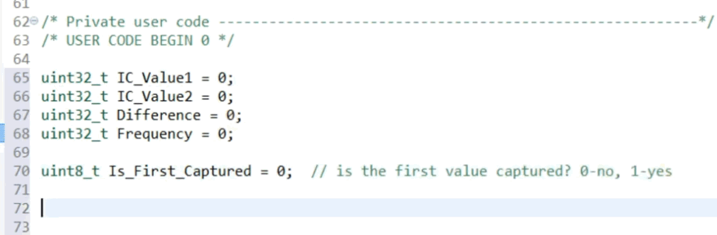
Controllers Tech declares a set of global variables at the top of main.c and initialises them to zero. Since we can rely on the C runtime to clear the RAM, this is unnecessary for globals and can use up code space and boot time. I would remove the initialisations unless it is thought likely that these lines would be moved into a function, making them local automatic variables, in which case they would need to be initialised. Local variables live on the stack which is a space which gets reused therefore you cannot rely on local variables being zero when declared.
Comparing the two captured values
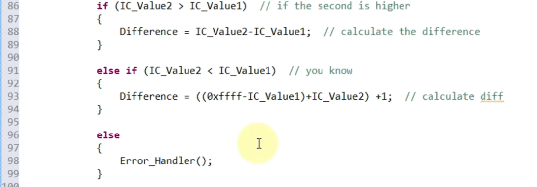
Controllers Tech's first condition (at this point in the video) is the expected case that the second value will be higher than the first, i.e. the timer has not rolled over. It is easy to see that the difference is simply the later value subtract the earlier value and there will be no problems with this expression. The second condition handles the rollover case where the second value is lower than the first value. This is correct but unnecessarily complicated. They calculate the difference by adding up
- the distance from the first value to the rollover value 0xFFFF
- the second value (which is from zero) and
- 1, to include the step from the rollover value to zero.
Firstly, this is only correct for a 16 bit timer. I decided to use TIM2 which is 32 bit, so that I could measure a wider range of frequencies. The minimum measurable frequency formula is (TIMx CLK)/ARR which is 42M/65536=640 Hz for 16 bit timer and 42M/4294967296 = 0.005 Hz for 32 bit timer. It would need changing to 0xFFFFFFFF for a 32 bit timer, which is an additional code change burden.
Secondly, the formula for calculating the distance between two values when they are the same size as the underlying counter, and are declared as unsigned, isDifference = IC_Value2 - IC_Value1;
which works irrespective of which value is the greater, i.e. it is the same formula whether there has been a wrap/rollover or not. Clearly this only works when there is at most one rollover - if it is possible to get multiple rollovers before you can capture the results, you must use a slower clock (this could be done with prescaling) or a bigger (number of bits) timer. To understand how this works when IC_Value1 > IC_Value2, think of subtraction as wrapping back over the same boundary in reverse by the same amount.
Thirdly, Controllers Tech treats the case of IC_Value2 == IC_Value1 as a special case requiring error handling. This will only occur if the clock has stopped, in which case no frequency measurement can be done; if the clock is so slow that two interrupts can occur without the timer moving, in which case the frequency is overrange; or if the timer value has exactly wrapped but this isn't explicity detected by the code so you can't say anything about the frequency. Personally, I would move the equals condition to one of the handled cases and then detect Difference being zero as the error condition.
So I would replace the 12 lines
if (IC_Value2 > IC_Value1){Difference = IC_Value2 - IC_Value1;}else if (IC_Value1 > IC_Value2){Difference = ((0xFFFFFFFF - IC_Value1) + IC_Value2) + 1; //used 0xFFFF for 16 bit regs}else{ErrorHandler();}
with 1 line
Difference = IC_Value2 - IC_Value1; //subtraction is correct regardless of direction as long as all vars are same size as registers and are unsigned. When IC_Value1 > IC_Value2, subtraction wraps back over the same boundary in reverse by same amount.As we know that in real time systems, interrupts should do the minimum amount of work necessary so that they are as fast as possible, I moved the divide for Frequency calculation to main line code.
Measuring duty cycle
In the above code, we were only looking to measure frequency, so the timer was left free-running and we had to do a subtraction to get the time difference between edges. A different technique is used when measuring duty cycle, where the timer is reset on each rising edge - Slave Mode = RESET. This can be done in the peripheral so that there is no interrupt latency involved (does not call an ISR and hence no context saving is needed), which gives a more accurate result. Channel 2 of the same timer is used to trigger on falling edge for the pulse width.
Performance improvement using DMA
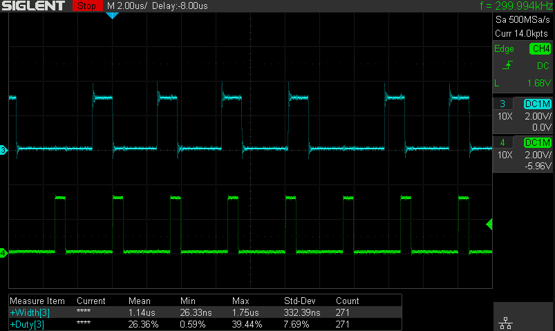
Above 300 kHz, I can see that the interrupt does not always occur for each pulse, so the frequency value becomes unstable. By learning about DMA from various sources including Edwin Fairchild, and reading the user manual UM1725 these code changes can be made.
Main line code to start and run the frequency measurement:
/* USER CODE BEGIN 2 */
HAL_TIM_IC_Start_DMA(&htim2, TIM_CHANNEL_1, t2halbuf, 1);
rccclk = HAL_RCC_GetPCLK1Freq()*2;
/* USER CODE END 2 */
/* Infinite loop */
/* USER CODE BEGIN WHILE */
while (1)
{
/* USER CODE END WHILE */
/* USER CODE BEGIN 3 */
if (Difference != 0)
{
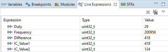
Frequency = rccclk / Difference;
if (IC_Value1 != 0)
Duty = (IC_Value2*100)/IC_Value1;
}
}
/* USER CODE END 3 */Interrupt routine to record the captured values:
void HAL_TIM_IC_CaptureCallback(TIM_HandleTypeDef *htim)
{//Frequency and Duty Cycle
HAL_GPIO_WritePin(GPIOD, GPIO_PIN_13, GPIO_PIN_SET);
if (htim->Channel == HAL_TIM_ACTIVE_CHANNEL_1) //rising edge
{
IC_Value1 = t2ch1halbuf; //first value
HAL_TIM_IC_Stop_DMA(&htim2, TIM_CHANNEL_1);
HAL_TIM_IC_Start_DMA(&htim2, TIM_CHANNEL_2, &t2ch2halbuf, 1);
}
if (htim->Channel == HAL_TIM_ACTIVE_CHANNEL_2) //falling edge
{
if (IC_Value1 != 0)
{
IC_Value2 = t2ch2halbuf; //falling edge
Difference = IC_Value1;
}
else
{
Duty = 0;
}
HAL_TIM_IC_Stop_DMA(&htim2, TIM_CHANNEL_2);
HAL_TIM_IC_Start_DMA(&htim2, TIM_CHANNEL_1, &t2ch1halbuf, 1);
}
HAL_GPIO_WritePin(GPIOD, GPIO_PIN_13, GPIO_PIN_RESET);
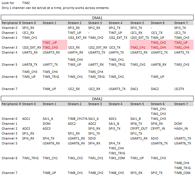
} Although the DMA runs independently from the CPU to copy values from TIM2 to the buffer, we still have to keep restarting the DMA on each interrupt alternately with the two channels and buffers to obtain the values for each edge because the streams for these timer channels share the same DMA channel (3).
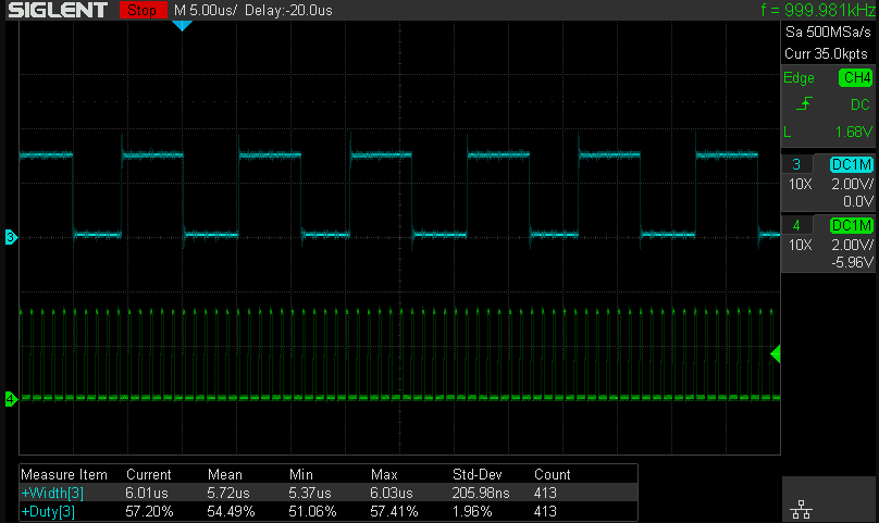
Interestingly, the DMA interrupt handler is taking longer (5.7us) than the Input Capture interrupt handler was taking (1.2us) so this in itself is not the cause of the performance increase. The important difference is that the Input Capture interrupt handler had to run on every falling edge otherwise it started to go wrong, but the DMA version quite happily works even if only triggers an interrupt every few cycles, as can be clearly seen above. The DMA method transfers the results as soon as they are available to a RAM buffer, freeing up the peripheral to start looking for the next trigger and the CPU can read from the buffer much later without any possibility of corrupted data.
Each Input Capture channel can be set to use a prescaler of 2, 4 or 8 to increase the maximum frequency that could be measured by that factor.