
Adding Brightness Control to the BLE Lightbulb Example
In the previous post on using a BLE peripheral example, the LED2 could only be controlled in terms of two states, On and Off. With my background of lighting controls, I wasn't satisfied that this could be called a BLE lightbulb project without at least brightness control. Since the example BLE code is already set up to send a byte as the BLE characteristic value, it should be easy to expand the example to brightness control in percentage terms using the byte in the range 0 to 100.
The main addition to the previous project is the PWM software module which sets up and controls the internal PWM hardware peripheral on the nRF52832. It is better to use an existing software module which encodes all the knowledge necessary to set up the PWM peripheral rather than just accessing the registers directly which would mean careful study of the datasheet with possible misinterpretation and that gives us an interface layer for future portability.
The first location I tried looking for a reference example was SDK\examples\peripheral\led_softblink but it was not suitable for a couple of reasons. led_softblink uses a low power technique for the PWM which involves setting up the PWM timer and then going to sleep until the next edge. It results in a low frequency PWM of 62Hz and the example code is overcomplicated by automatically cycling between dimming up and down, and it's use of low_power_pwm.c. It does not use the hardware PWM module.
The next location I tried was SDK\examples\peripheral\pwm_driver which does use the hardware PWM module but is also complicated by the different blinking patterns and use of DMA and sequences, which a feature of the PWM module where the duty cycle can be automatically varied over time.
Finally I tried searching the Nordic forums and found pwm_simple.zip which was not using DMA and sequences, and uses the PWM hardware module. It shows how to add PWM to a project, and is easily adapted to our use in the BLE Lightbulb example.
Modules and Channels
The nRF52832 has three PWM modules. These can be enabled in sdk_config.h using #define NRFX_PWM0_ENABLED 1 and similar PWM1 or PWM2 for the other two modules. There is also a corresponding #define PWM0_ENABLED 1 definition with PWM1 and PWM2 for the other modules. In this example we are using one module, PWM0, but it has four channels, so the seq_values array has 4 values and we can see the 4 channels in the Register view, each having a PIN and a CONNECT status.

Adding PWM files to Project
In SES, within the project, within the nRF_Drivers folder, Add Existing File, browse to and addSDK\modules\nrfx\drivers\src\nrfx_pwm.c
In sdk_config.h, enable PWM support by finding and changing 0 to 1 for the following #defines
#define NRFX_PWM_ENABLED 1
#define PWM_ENABLED 1
#define PWM0_ENABLED 1
Code Updates
These are from pwm_simple.zip by Nordic Semi.
Add near the top of main.c
#include "nrf_drv_pwm.h"

static nrf_drv_pwm_t m_pwm0 = NRF_DRV_PWM_INSTANCE(0);

// Declare variables holding PWM sequence values. In this example only one channel is used
nrf_pwm_values_individual_t seq_values[] = {0, 0, 0, 0};
nrf_pwm_sequence_t const seq =
{
    .values.p_individual = seq_values,
    .length          = NRF_PWM_VALUES_LENGTH(seq_values),
    .repeats         = 0,
    .end_delay       = 0
};

static void pwm_update_duty_cycle(uint8_t duty_cycle);
Later in main.c, add these two functions
static void init_pwm_LED2_brightness(void)
{
    nrf_drv_pwm_config_t const config0 =
    {
        .output_pins =
        {
            BSP_LED_1 | NRF_DRV_PWM_PIN_INVERTED, //PWM channel 0, using pin 18
            NRF_DRV_PWM_PIN_NOT_USED, // PWM channel 1
            NRF_DRV_PWM_PIN_NOT_USED, // PWM channel 2
            NRF_DRV_PWM_PIN_NOT_USED  // PWM channel 3
        },
        .irq_priority = APP_IRQ_PRIORITY_LOWEST,
        .base_clock   = NRF_PWM_CLK_1MHz,
        .count_mode   = NRF_PWM_MODE_UP,
        .top_value    = 100,
        .load_mode    = NRF_PWM_LOAD_INDIVIDUAL,
        .step_mode    = NRF_PWM_STEP_AUTO
    };
    APP_ERROR_CHECK(nrf_drv_pwm_init(&m_pwm0, &config0, NULL));

}

// Set duty cycle between 0 and 100%
static void pwm_update_duty_cycle(uint8_t duty_cycle)
{

    // Check if value is outside of range. If so, set to 100%
    if(duty_cycle >= 100)
    {
        seq_values->channel_0 = 100;
    }
    else
    {
        seq_values->channel_0 = duty_cycle;
    }

    nrf_drv_pwm_simple_playback(&m_pwm0, &seq, 1, NRF_DRV_PWM_FLAG_LOOP);
}
Change function led_write_handler()
static void led_write_handler(uint16_t conn_handle, ble_led_service_t * p_led_service, uint8_t led_value)
{
    if (led_value <= 100)
    {
        pwm_update_duty_cycle(led_value);
        NRF_LOG_INFO("Received LED value %d%%", led_value);
    }
    else
    {
        NRF_LOG_INFO("Received LED value out of range %d%%", led_value);
    }
}
In main(), after other init functions, add
//PWM for LED2
init_pwm_LED2_brightness();
Debugging
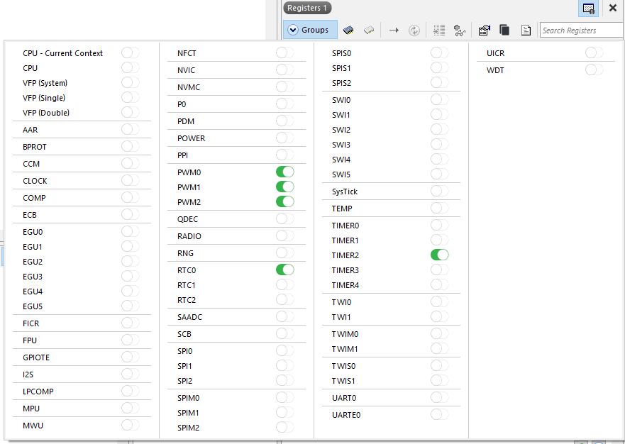
When first converting pwm_simple to this project, I was trying to find out why the PWM was not running on the output. It was useful to use the register view and switch on the PWM Groups to see how the chip was set up. That allowed me to see that the PSEL.OUT[0].PIN was not set to 18 (0x12) which corresponds to LED2 on the DevKit called P0.18
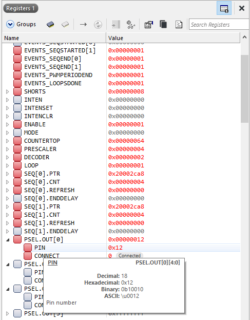
This was due to a misunderstanding about the config0 structure with the 4 elements in output_pins. They represent the PWM channels inside one module, and are not related to the 4 LEDs on the dev board.
Compilation Statistics
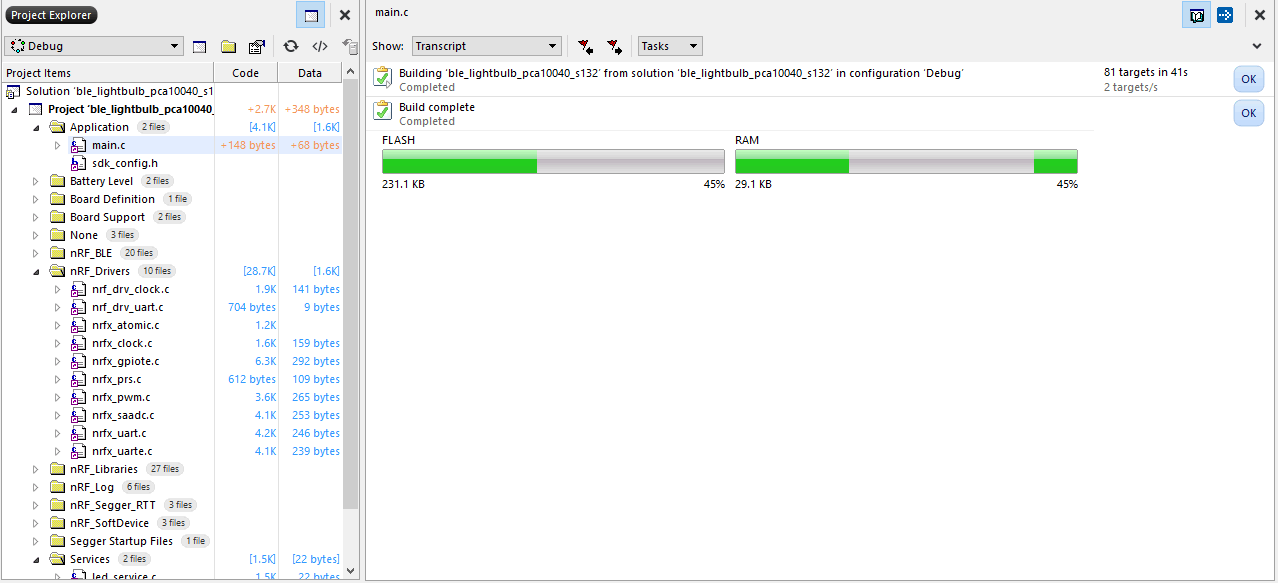
Comparing the On/Off feature build with the PWM build, using SDK16.0
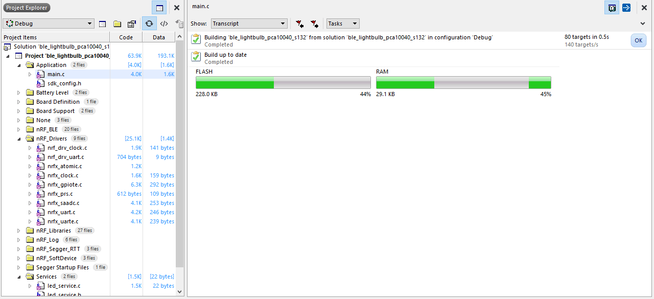
| Flash kB | RAM kB | |
| On/Off Only | 228.0 | 29.1 |
| With PWM | 231.1 | 29.1 |
So PMW requires additional 3.1k Flash.
Testing
nRF Connect for iOS allows the LED Characteristic value to be written
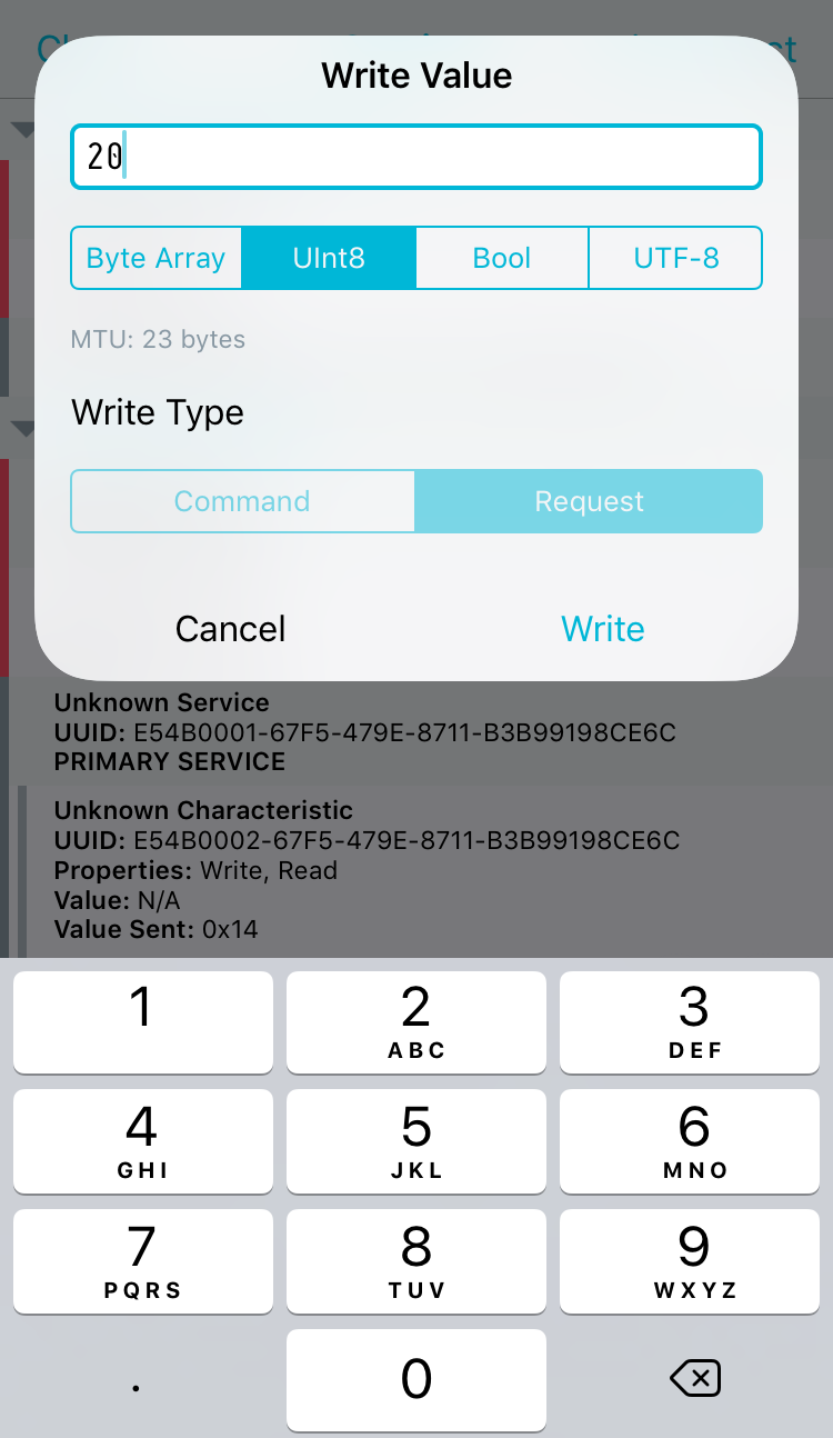
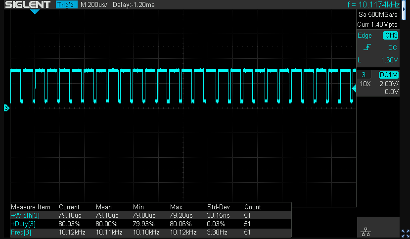
Due to the way the LED is connected in the dev kit as active low (current sink), the brightness values are inverted, hence 20% brightness requires 80% PWM as shown above.
Sending 0 achieves full off and 100 achieves full on with no minimum or maximum PWM duty cycle restrictions visible. The PWM frequency is 10 kHz.
To turn this into a lighting-industry suitable design would require adding variable length fades, dimming curves and scenes. These features are left as an exercise for the reader.