
Using and Misusing CRCs
CRCs are used for error detection in communication systems and storage systems. They have a combination of several advantageous properties whilst only requiring a short FCS, but they do have their limitations. If you require error correction as well as detection then you have to look at a different class of algorithms and will have to add much more redundancy to the codeword.
The rest of this post is about message systems, where if an error is detected, the link layer of the protocol will take various actions such as discarding the message, sending a NACK, requesting a retry, waiting for retry until a timeout occurs etc. Another use of CRCs is for protecting data in memory, where similar considerations apply but the corruption possibilities may be different so you have to consider if the single random bit-flips model is still appropriate. If you just need to protect a single 8, 16 or 32 bit value, choose from this list and use a non-zero seed.
When Using CRCs...
1. Protect the Length field
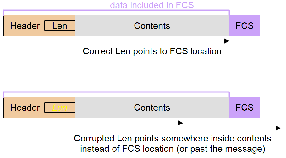
Unless your protocol design is such that the messages are fixed length, one of the fields in the message will be the message length or an equivalent which points to the position of the FCS. Since this field is also subject to random bit errors, it is a mistake for the receiver to trust this field before the CRC has been calculated and compared, and yet it needs to use the length field to isolate the FCS from the rest of the message so that it can be compared to the calculated CRC.
If the length field gets corrupted it will point to the wrong location in the message (or even outside it!) for the FCS, so instead of using the real FCS the receiver will use part of the message or some other part of RAM. This results in a 1 in 2^n probability that the CRC test will pass (where n is the number of bits of the FCS) so the HD is reduced to 1 irrespective of how good the HD of the real CRC is.
An unprotected length field is a bug in the design of many standard protocols including HDLC, and CAN.
In some protocols, a message type field implies the length (which is then looked up based on message type) rather than there being an explicit length field. This can suffer from the same problem but there may be some saving in that the number of message types is likely to be small, which increases the possibility of detection of corruption there, and corruption to another valid message type can cause subsequent message rejection if the payload values are not within expected ranges.
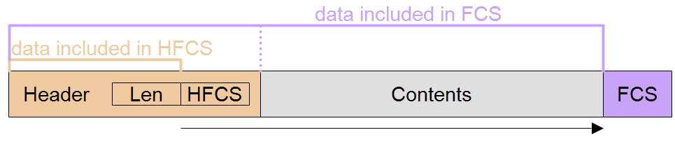
The best mitigation for this is to use an independent FCS for the length field, or on the header which includes the length field.
Although this CRC can be smaller in bit-size than the payload CRC since it is protecting a smaller number of bits, it must be selected to have the same HD as the payload CRC to maintain the overall HD of the message. Otherwise the overall HD is reduced to the smaller value of the header CRC's HD.
Other mitigations are simple parity bit on the length field or header which includes it, and tests for the number of bytes received match the length field (as long as they are not otherwise forced to match). If you use this second option, you should test that your length test works using deliberately corrupted frames.
Note that these mitigations assume the header itself is a fixed length.
2. Don't put FCS at start of message.
It might seem like a good idea to solve the length field problem to always put the FCS before the payload but this is not recommended.
The golden rule is that the bits must be processed by the CRC calculation in the same order as they are sent on the bus so that a burst error does not get split up and spread out.
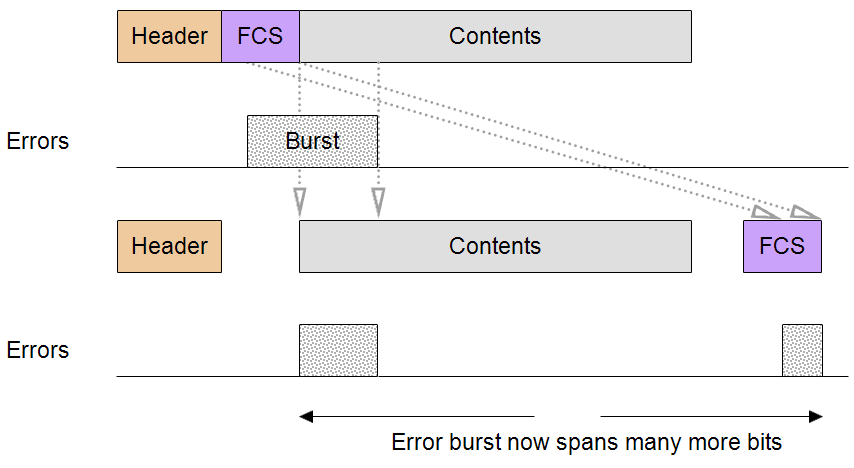
By moving the FCS to the start of the message, you are imposing a requirement on the receiver to process it before the first byte of payload. If there is no FCS post-processing required that could work as long as the receiver treats the FCS and subsequent payload as one long bit stream and therefore the final comparison is with zero.
However, if FCS post-processing is required this scheme will not work because the FCS is being used at both the beginning and end of the processing. To avoid this potential problem and allow for post-processing, design the message so that the FCS is at the end.
3. Don't change the byte or bit ordering of the FCS with respect to the payload
The FCS format must follow the payload format to preserve the burst error protection (of n bits that an n-bit CRC gives you).
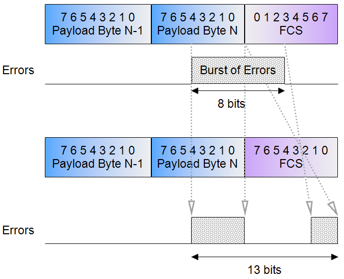
Example showing that if FCS has a reversed bit-order from the payload, an 8-bit CRC can no longer detect an 8-bit error burst because it spans 13 bits after bit order reconstruction in receiver.
4. Take care with any bit manipulation after computing the FCS
Only a few operations have been proven to not affect the error detection properties of the CRC. A bitwise NOT is ok, as is the more general case of an XOR operation on the FCS with a fixed value. But bit-stuffing a la CAN has been found to be a problem and 8b10b encoding a la Gbit Ethernet might be a problem. Testing with Gigabit Ethernet encoding shows that if malformed physical 10b encodings are rejected the CRC performances seems not to suffer, but not all hardware acts so strictly. By altering the decoding to make the best of what arrives, errors can occur which are undetected by the CRC.
5. Scramblers will induce problems unless the scrambler bit-size is less than the CRC bit-size.
Whilst it might be possible to mitigate the bit-stuffing problem by calculating the CRC post-stuff, there would then be the problem of the FCS field needing to be stuffed, so the recommendation is to avoid bit-stuffing if HD > 2 is required.
Don't apply compression after computing the FCS. The interaction between compression, encryption and error detection is poorly understood by researchers in the field.
Line coding can interfere with the operation of the CRC and need to be very carefully evaluated, don't assume it has no effect.
6. Don't assume that multiple error codes will make the improvement that you desire
Attempting to increase protection by using multiple FCSs on the same message is unlikely to achieve it's aims. It has generally been shown that use of one larger CRC e.g. 32 bit is better than two smaller e.g. 16 bit ones because of the problem of common factors, but even without those, Koopman found many 4-bit errors got past both.
Multiple error codes do not usually increase the Hamming Distance but can reduce the undetected error fraction. Usually the resulting HD is the lowest HD of the FCSs used. But there are some special cases where an improvement is significant, including the case of an overall error code covering smaller, individually protected code words. In other words nesting is better than multiple overall error codes.
7. Use a non-zero initial value
This has two advantages and is cheap to implement. It makes an all zero message (code word) impossible, so you can detect that as an additional fault state which can be interpreted as a physical layer fault condition such as an open circuit. The second advantage is that leading zeros in the data word affect the FCS value so you can detect when leading zeros have been dropped or inserted.
Bit values are more often zero than one in many networks for at least two reasons:
- to allow sufficient overhead, values are typically much smaller than the field size (variable size) that contains them,
- unused fields default to zero.
If you need to detect data ordering problems within the packet, use a sequence number that is itself protected by a CRC, rather than relying on the overall message's CRC. This is basically the same issue as protecting the length field in the header.
Don't misuse CRCs...
1. Choosing CRC size or polynomial for the wrong reasons
Previously covered here and here.
2. CRCs cannot be used as if they were cryptographic protection
The aims of CRCs (error detection) and cryptographic hashes (tamper detection) are in some ways opposites so this is a bad idea. It is very easy to alter a payload to get to the same FCS value as the original, or to alter both the payload and FCS to pass the CRC calculation.
“I'll just use a CRC to detect if any bits have been tampered with. There's hardware support for CRCs so it'll be fast too.”
You cannot increase the security by using such ideas as initial values and post-processing the FCS with an XOR operation because this does nothing to affect the number of combinations, which is solely down to the bit-size of the FCS. In fact, the CRC RevEng project shows that it is possible.
3. Don't use a cryptographic hash instead of a CRC.
Despite their larger bit-sizes, cryptographic hash functions do not give you enhanced performance from a detecting bit errors point of view, in fact they are much worse because they only give you an HD of 1. This makes them very inefficient for this job and worse than simple parity with HD=2. With their HD of 1, some 1-bit errors will be undetected and they have no burst error coverage guarantee in principle.
Of course you might need to use one in addition to a CRC, to detect tampering.
4. Don't put the CRC inside an encrypted payload.
If you put the CRC inside the encrypted payload you have to decrypt before running the CRC calculation. The decryption has the effect of spreading any errors from transit across the payload which reduces the HD to 1. Put the FCS outside the encrypted payload and it should be run on encrypted data because that is the bit stream that is transmitted and subject to errors.
A value inside an encrypted payload which is designed to be used as an integrity and authenticity check is called a Message Authentication Code.
5. CRCs cannot be used as an addressing method.
It is tempting to use some of the parameters in the CRC algorithm such as initial value, initial or final XOR pattern as an address filter. In other words, if a message arrives that fails the CRC check with one value of the parameter but passes with the other, this means it was sent from/to a second address. It is a bad idea because it will reduce the Hamming Distance. In other words, a corrupted message may fail to match the first "address" but by accident match the second "address". Using different initial values on one communications channel would prevent the system from properly counting detected CRC errors which can be a useful statistic.
However, this could be a valid approach to detect cross wiring of one communications channel with another, or of connection of a foreign device; cross wiring/the foreign device would produce almost 100% error rate and correct wiring/known devices would work as normal.
The difference between these applications is that in the first case, we expect 100% reliability of the system to address messages correctly, but in the second case we have much lesser expectations - it is good enough to detect cross wiring/foreign devices with only some of the time because this is a fault condition and correct and reliable system operation is therefore not expected.
6. Don't truncate a FCS value.
If you don't have space for a 32-bit FCS but only have space for a 16-bit FCS, use a 16-bit polynomial. Do this even if that means more consuming more code space because you already have a 32-bit CRC calculation routine elsewhere in the product. You get a worse result by using 16 bits of a good 32 bit CRC than you would do by using a good 16 bit CRC. In other words, a 16-bit FCS is not the result of truncating a 32-bit FCS, they are different things.
Don't make an 8-bit FCS by chopping a 32 bit one, take Mark Adler's advice.
7. Don't make expectations of CRCs that they can't supply
Whilst CRCs are the best choice for error detection (compared to other checksum methods), bear in mind their useful range of operation:
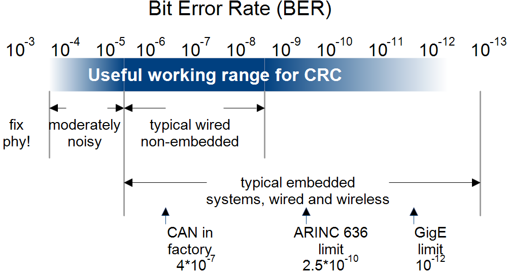
- Bit Error Rates roughly in the range of 1e-4 to 1e-12.
- Errors are independent randomly distributed bit flips and/or a single bust of n bit flips within a message
- In applications where error detection is sufficient (not correction), because the system can recover from the state eg by retries or can afford to discard some messages
- Small FCS field is needed because the codeword size is tightly constrained
- Low computational overhead
- HD >= 2 for all data lengths
- HDs of 3 to 6, mainly
- Probability of Undetected Errors is independent of the data word value
but they have limits. They don't have the same Pud guarantees if noise is non-random e.g. repeatable, systematic, data dependent, maliciously manipulated. Examples of where they would not work so well:
- systematic bit slip e.g. due to sampling jitter or RTOS task duration variations
- PSU noise (regular repeats)
- coupling from other cables/systems/RF, particularly if synchronized
- asymmetric bit flips due to hardware thresholds, biasing or transceiver design
Don't expect CRCs to compensate for poor physical layer performance when high BERs are present.
Whilst the probability of undetected errors in a message after a CRC verification is very low, there is no guarantee about specific fields inside the payload being not corrupted, irrespective of their size.
Just because the message passed it's CRC verification does not mean you can omit range checks and sanitisation to data in that message arriving over a comms link - sizes, lengths and array indices are a particular concern.
8. Don't use a disproportionately large FCS
By adding bits to the codeword, there is an increased possibility of the codeword having an error in it, so you can end up rejecting a valid data word because of interference in the FCS field. This effect should discourage the use of disproportionately large FCS for small data words that could otherwise provide very high HDs. In other words, as is usual in engineering, there is trade off and large FCSs don't come for free even if computational resources are not the limiting factor.
9. Don't use a constant FCS to force an error at the receiver
If a transmitter gets into a problematic state where it is unable to send the message that it would normally, such as being unable to resend a message because of a buffer underrun, then it may attempt to cause the receiver to ignore the message by sending it with a bad FCS. It is tempting to just pick a constant FCS value, such as zero when in this situation, or allow the FCS to be zero by leaving it unchanged, having previously cleared that value in memory. However, there is some small chance that this FCS will match the data word, leading to an undesired acceptance of the message by the receiver. The safe thing to do is to bitwise invert the FCS to maintain the Hamming Distance between the data word and the FCS.
The problem with using a constant FCS is acknowledged in the USB 2.0 specification section 8.6.4.
10. Don't use the FCS for framing
Although there is precedent for using the FCS for framing in Asychronous Transfer Mode and similar protocols, it is easy to get into difficulties with this technique. Bear in mind that the size of the FCS will affect how often it will occur naturally/randomly in the data, leading to false framing events.
Whilst this is tempting from a message overhead perspective, it incurs a high computational cost at the receiver since multiple CRC calculations have to be performed on a sliding window over the received buffer. Because the framing marker cannot be arbitrarily chosen to be an unlikely data pattern, there will be instances of the framing marker being a highly likely data pattern such as 0x0000. The mitigation for that problem is to train the receiver until the framing marker position is stable and to use hysteresis to maintain lock in the presence of errors but this shows up the inherent weakness in the idea.
What error types occur in practice?
All the CRC evaluation is done on the basis of single independent rare bit flip type errors, with an equal probability of both polarities of error. This is a reasonable model for the phenomena of spike noise, where very small amounts of energy are necessary to produce very short changes in the signal level which might coincide with sampling point. These are the sort of spikes that IEC 61000-4-4 is designed to test immunity against, so there is some support behind this being a realistic noise type. What I mean is that the committee behind IEC 61000-4-4 did not choose their waveform parameters without a lot of background research into what occurs in real systems, so although the noise had to be idealized for standardization purposes including being reliably reproducible, the fact that it is in a standard means that there is evidence that this is somewhat typical of the noise which exists in real systems.
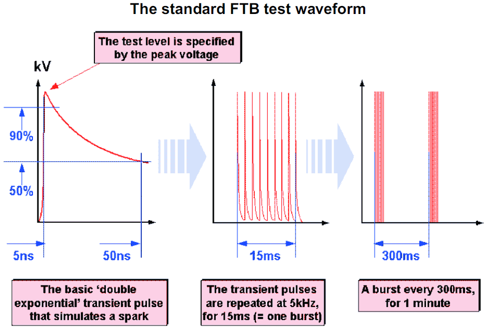
diagram from emcstandards.co.uk
However, when you think about it, the likelihood of a noise spike affecting just one bit is very small because the noise source is independent of the message bit times. There is no reason that the noise spikes should be just a bit less than the width of bit times to cover the case of multiple samples per bit (eg UART is typically 16x oversampled) or that it should coincide with the single sample of the bit (usually mid bit). There are, of course, unfortunate cases where the noise source is another signal on a nearby cable, with particularly fast rise/fall times and was at an integer multiple of the bit times, it would very often coincide with sample points. But in that case you would expect a BER greater than 1e-4, which means that more attention should be paid to the physical layer to fix this before resorting to error detection techniques.
Noise is more likely to affect a series of bits than just one at a time, and that is exactly where CRCs have their strength.
Whilst you would expect that the first priority is to choose a CRC size big enough to cover the burst, it turns out that the most critical factor is the Hamming Distance for the length of the message, followed by the Hamming Weight (number of undetectable errors).
Koopman lists other error types that should be taken into consideration:
- erasure burst - this is non symmetric as opposed to the usual BER model where it is equally likely to change 1 to 0 as 0 to 1, erasure bust will change all bits to 0.
- random data - noise is strong enough to force its own pattern on the data, regardless of the original signal. Possibly more likely during inter-message gaps.
- leading zeros - unexpected extra zeros occur at the start of the data, symptomatic of bit synchronization problems
- bit insertion/deletion - bit synchronization problems, clocking problems
- bit slip - bit synchronization problems, clocking problems, baud rate tolerance (which I've analysed previously).
If the BER approaches the 1/(number of bits in message), almost no messages arrive error-free and other problems occur in the message format decoding, commands not matching the list of ones handled and the next layer up handshake failures. Physical layer corrective action needs to be taken to restore the BER back to a reasonable level for the system rather than going for stronger error handling mechanisms.