
Sampling a Pulse Stream Mid Bit When the Clock Frequency Varies
- The micro has no UARTS, or the ones it has are already used.
- The pin can't be assigned to UART receive function - simpler micros have fixed pin functions; even in more complex micros not all pins can be mapped to any function.
- The base clock doesn't allow for the right UART clock rate with any of the possible divider options.
- The bit stream doesn't correspond to UART format, for example - more than 9 data bits, Manchester encoding, non-standard number of start and stop bits.
- The bit stream has a wide variation in pulse width which is outside the UART capabilities (typically 2.2%)
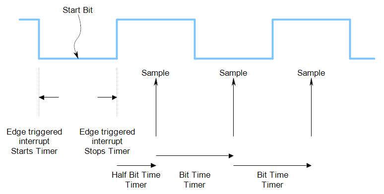
In these cases, the usual approach is to use an edge triggered interrupt to start a timer, measure the start bit, and then use the timer to sample in the middle of all subsequent bits. The success of this approach depends on the variation in the pulse widths and the number of bits in one frame.
To be clear, I am talking about purely digital signals at this point, not taking into account noise, ringing, ground bounce or interference.
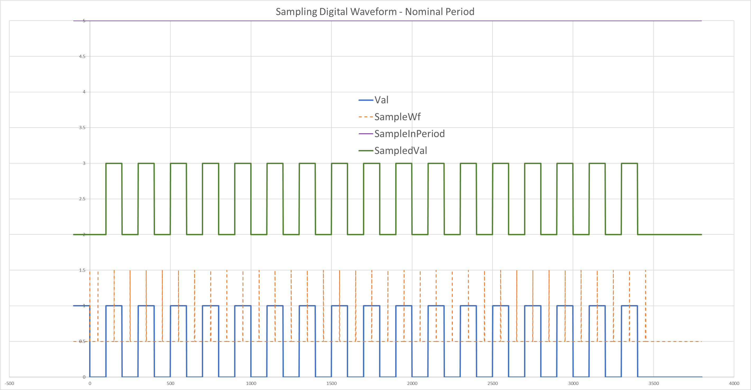
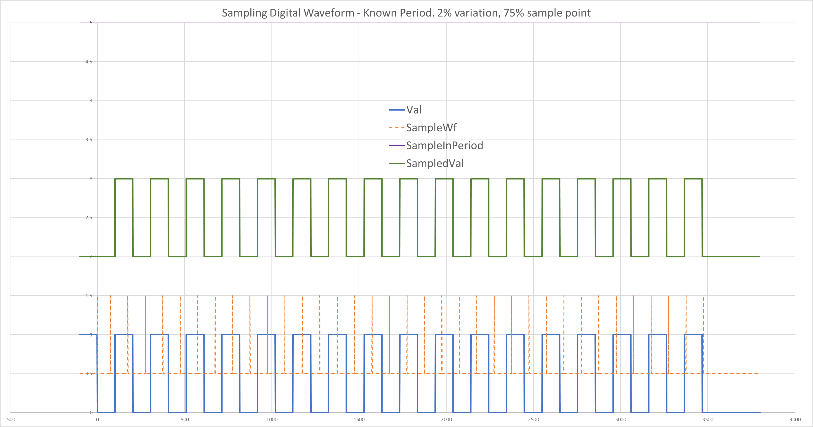
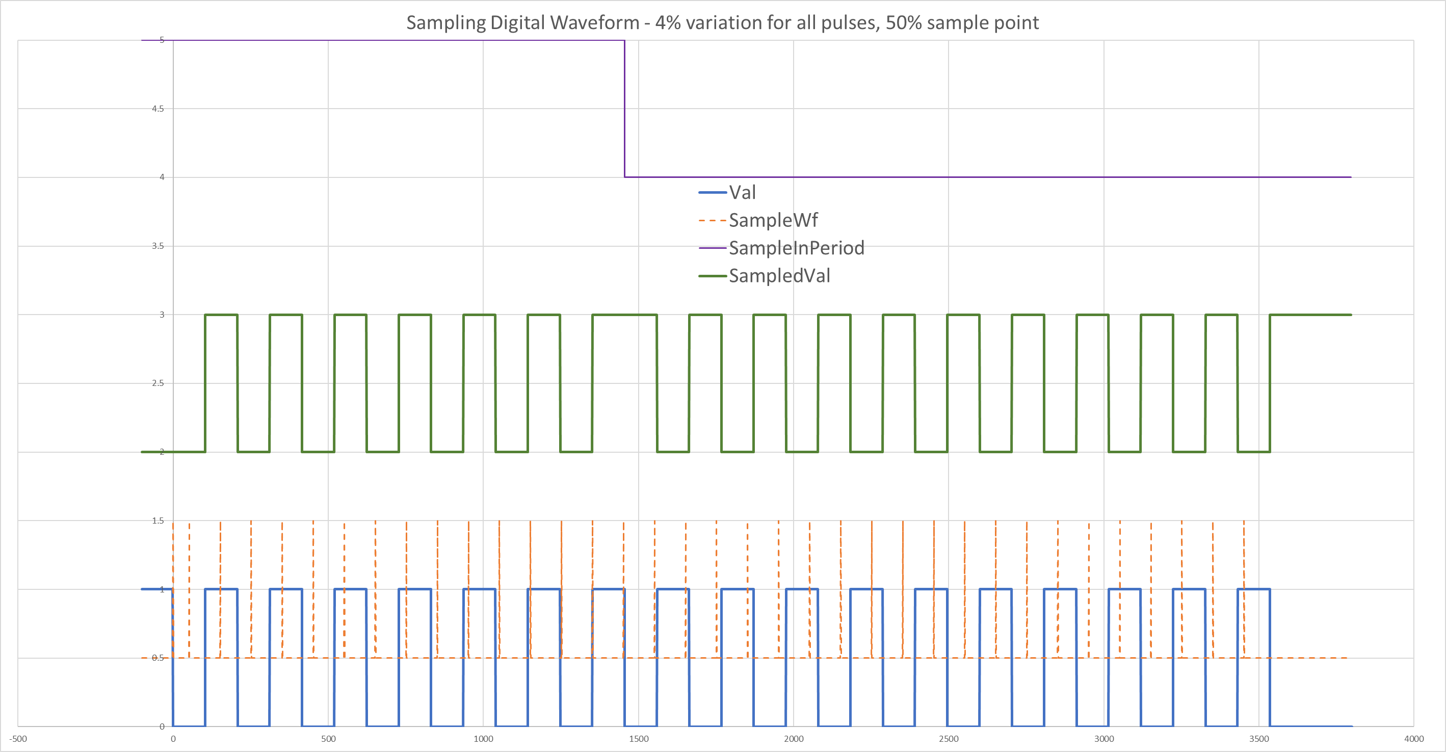
The blue "Val" waveform is the original signal, with the orange "SampleWf" spikes showing the sample points, offset by 0.5 vertically to seperate it from the original waveform. Above that is the green "SampledVal" waveform which is how the micro would reconstruct the waveform from the samples, so it includes points before the sampling point in each bit so that we can align the two waveforms to see that they match. The top purple "SampleInPeriod" waveform is high throughout this example, meaning that all the sample points have the correct value. We see this go low when we look at examples with wrong sampling points.
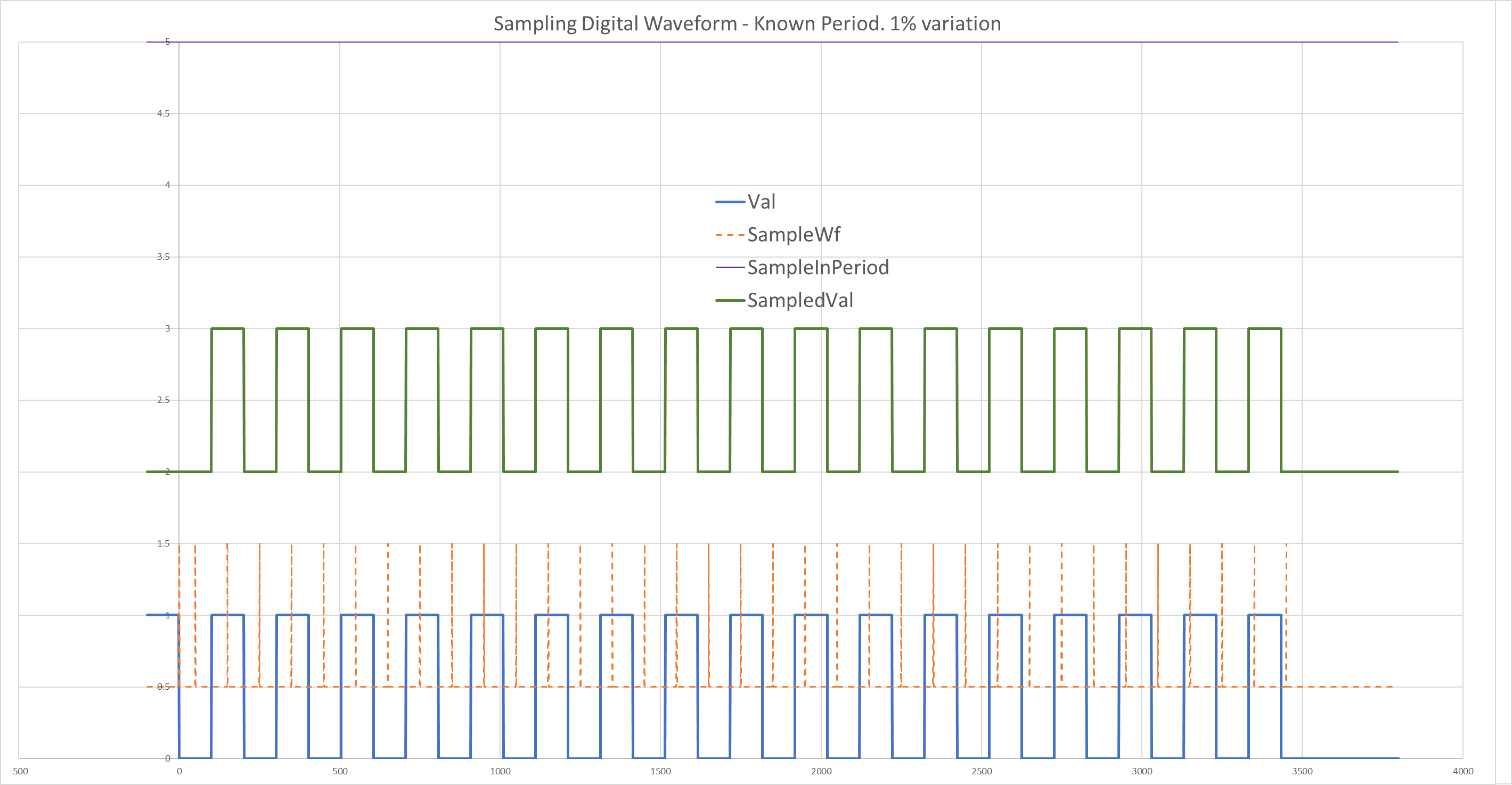
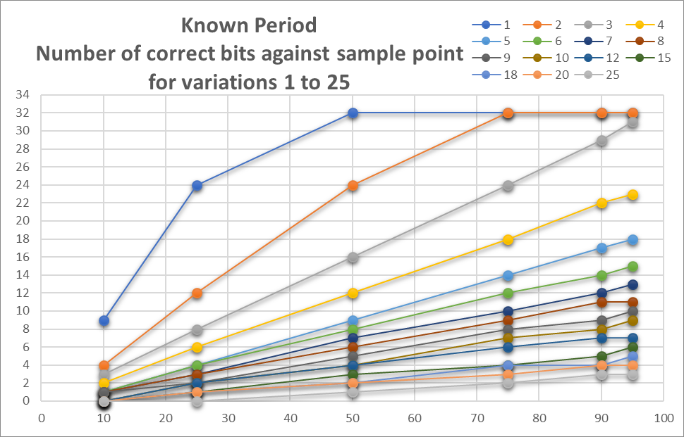
Let's see if we need to measure the start bit, it might be simpler to just use a hardcoded value that we are given for this signal type. Then we would just use the edge triggered interrupt to start the timer, and use a fixed timer interval. It turns out that if we sample at the 50% point, we can only be assured of getting all the bits sampled correctly if there is less than 1% variation in the clock between the bit stream and the sampling clock, for a 32 bit frame.
If there is 2% difference in clocks, sampling at the 50% point only works correctly for the first 24 bits before the sample point has slid off into the next bit. At which point, we get two samples in one bit period when the software is set up to assume each sample is in a different bit period.
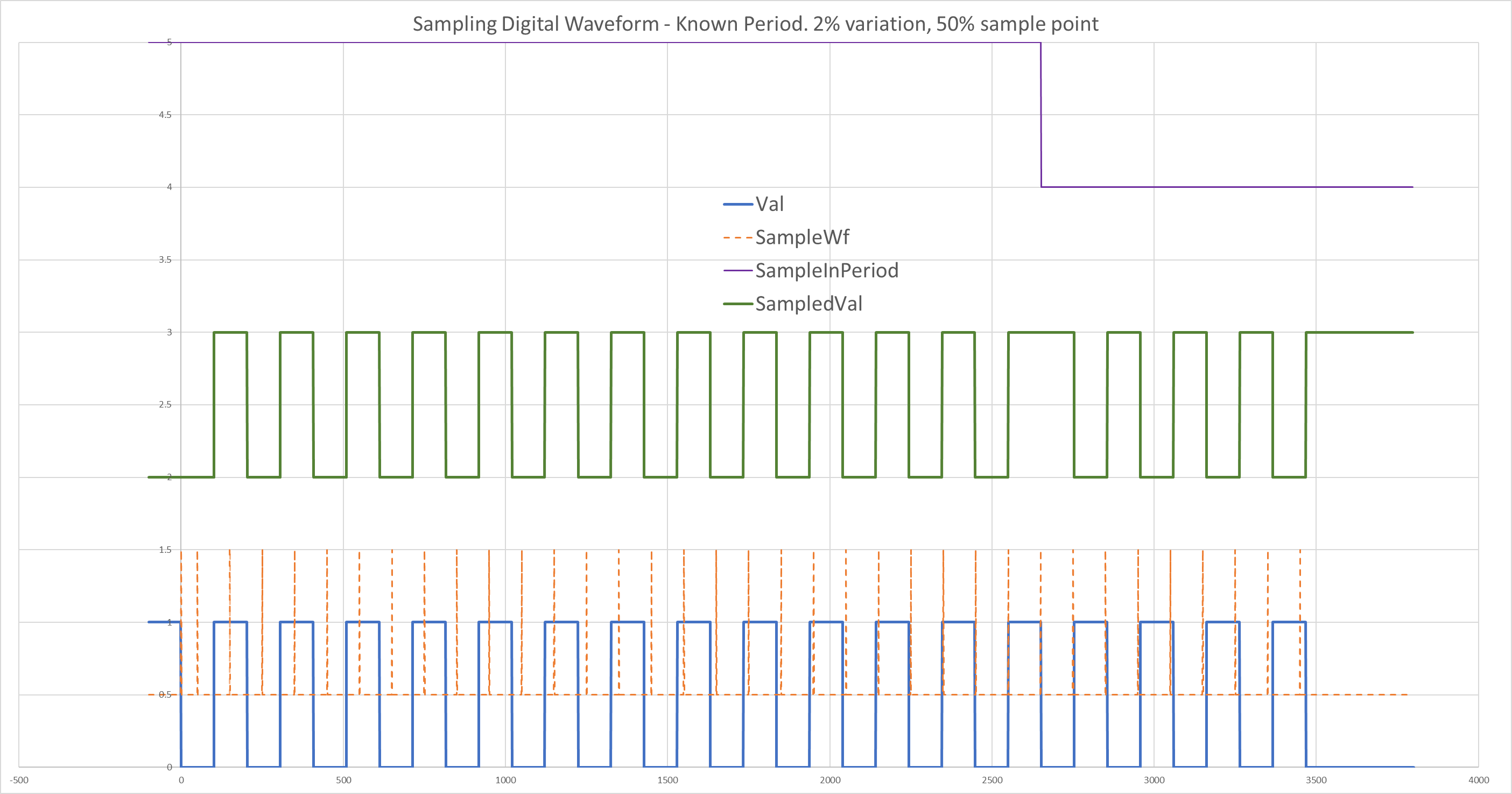
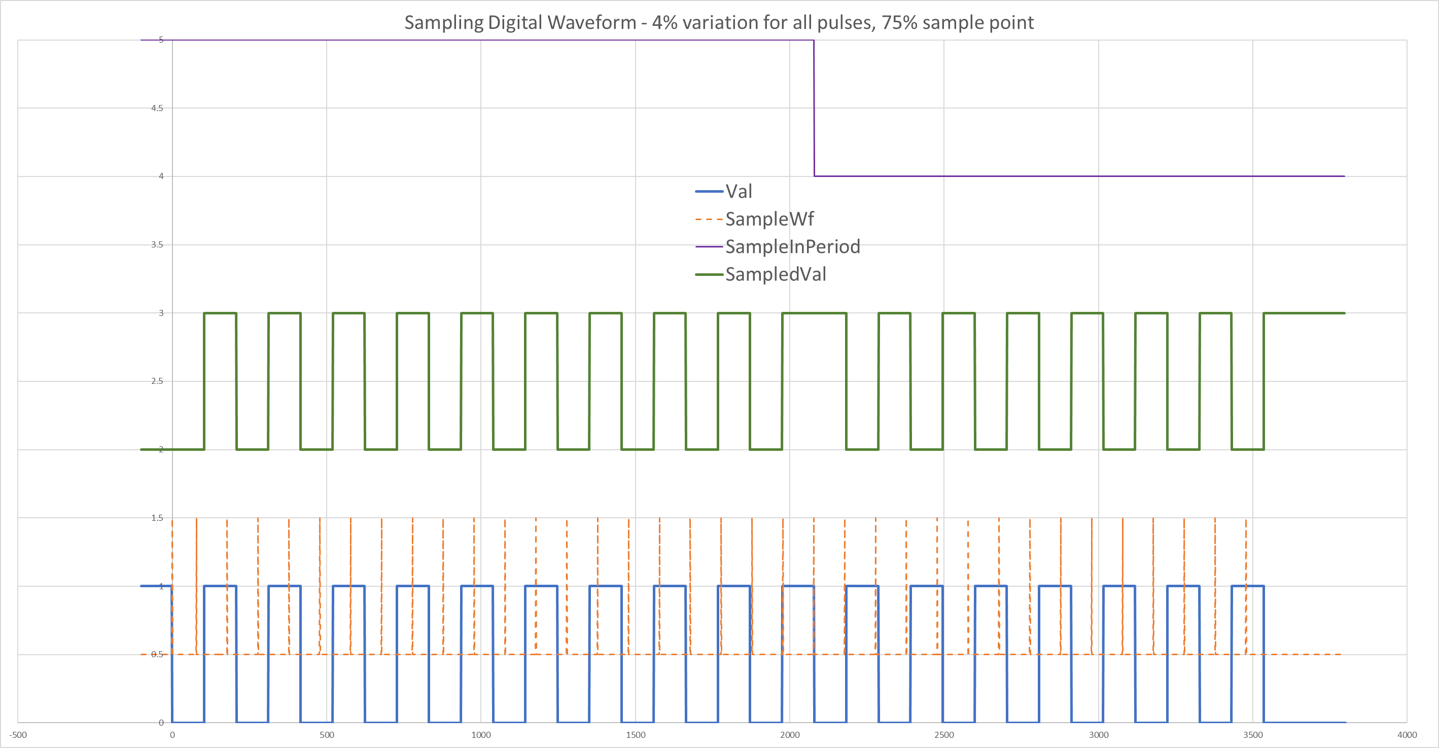
Moving the sample point to 75% of the bit time improves this so that all 32 bits are sampled correctly.
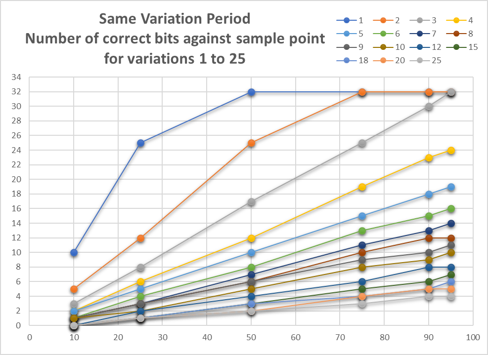
You would expect that measuring the start bit would allow for more bits to be sampled correctly at the same clock difference, or equivalently, that more clock difference can be tolerated for the same number of bits. The 2% difference in clocks case with 50% sample point gives us 25 bits correct, so that is only one more bit, a slight improvement.
A significant improvement is always made by sampling further than 50% into the bit time. In practice, using values higher than 95% are likely to lead to problems with jitter in the sampling point taking you into the next bit period randomly.
The conclusion from this is that it is a good idea to keep your bit length short, if you are using this decoding technique, to allow for clock variation. Otherwise you will need to synchronise to the edges more often, such as at every edge or alternate edges, bearing in mind that edges may not appear for long runs in NRZ encoded data.
This analysis explains a problem I saw many years ago in a situation where an infra red handset signal was unreliably received. Both the sender and receiver were using PICs with internal RC oscillators such as the PIC16F505.
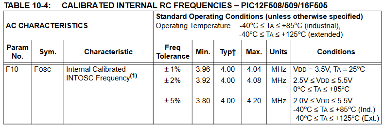
We found that some receivers would work with some handsets, but not all receivers would work with all handsets. The handsets were battery powered by two 1.5V batteries, so there would be some voltage variation as they discharged with usage. Although the receivers were on a regulated supply, they would still have part-to-part variation in the clock frequency.
This problem was a mystery initially because the design had worked fine for years, and the only thing that had changed was the IR protocol. So it appeared to be a data dependent hardware bug, which is always an odd thing to have to deal with. But this analysis shows exactly what went wrong, because the change to the IR protocol was to go from 8 bits to 16 bits! The thinking behind this change was that a single byte value could have been corrupted by noise (IR is often modulated at 38kHz which unfortunately is also emitted from high frequency fluorescent lighting) so instead of just adding a single parity bit, a whole check byte was added. In theory, this would mean that it would be much harder for the signal to be corrupted, and yet the reliability was worse for the 16 bit version.
My analysis shows that with the sort of variation we would typically see in such a pair of micros of 4% (say one at +2%, one at -2%), sampling at 50% into the bit, you can only get 12 correctly sampled bits, not the 16 that we needed.
But now we can see that a solution would have been to move the sample point to 75% or more, which gives us 19 correctly sampled bits. Actually, 65% is just about the minimum sample point for 16 bits but there is no good reason to use a value this tight, so anything in the 75% to 90% region would be optimal.
In practice, there was an additional problem with the hardware. The longer frame, in conjunction with a very low series resistor for the IR LED to get higher pulse currents and hence better range, meant that the battery voltage had collapsed by the end of the frame causing the micro to get near or into its brown-out or even its reset voltage. It wasn't fixable by adding a large capacitor across the supply; but increasing the LED resistor did help since it reduced the voltage dip. Another possible fix would have been to reduce the duty cycle of the modulation - with IR LEDs, 5-10% duty cycle is just as effective as 50% and does not reduce the range.
Of course UARTs solve this by using an overclocking scheme, typically taking 16 samples per bit period and using a majority voting scheme to allow for some of the sample to be in error, whether due to timing or noise.
Finally, I can show that when the pulses can vary in width within a wide tolerance, it is not possible to find a sampling point that works correctly for 32 bits in the incoming stream. For example, here is a bit stream that varies by up to 20% but often only by 10%, and even with a run of nominal 0% pulses, still cannot be sampled correctly using one mid bit sampling point, whether the sampling point is at 50%, 60%, 75% or 90% of the measured bit time.
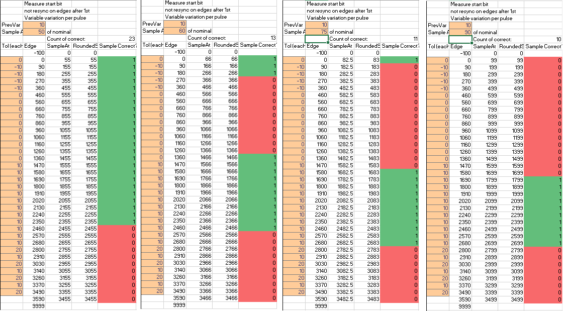
Therefore in such cases, we need to use a different decoding technique such as measuring the width of all pulses, and/or multiple sampling points per bit. My spreadsheet can help you decide when you need to change to the more advanced techniques and what the bit length limitations are in your situation.