
Countdown Timer for Children's Games: Firmware Design
In the first of these four blog posts on the firmware for the countdown timer, we'll look at the firmware layer design, the user interface functions and power consumption. The bargraph LEDs, buttons and switches are just GPIOs driven through my hardware independent driver layer, but there's more of interest in the seven segment display driver and speaker driver. Since there's no such peripheral as a seven segment display driver, at least not on this micro, I've had to write one. Driving the speaker with PWM proved slightly more difficult than you might expect, and there's some niceties around the sound that I wanted to include.
Layer Design
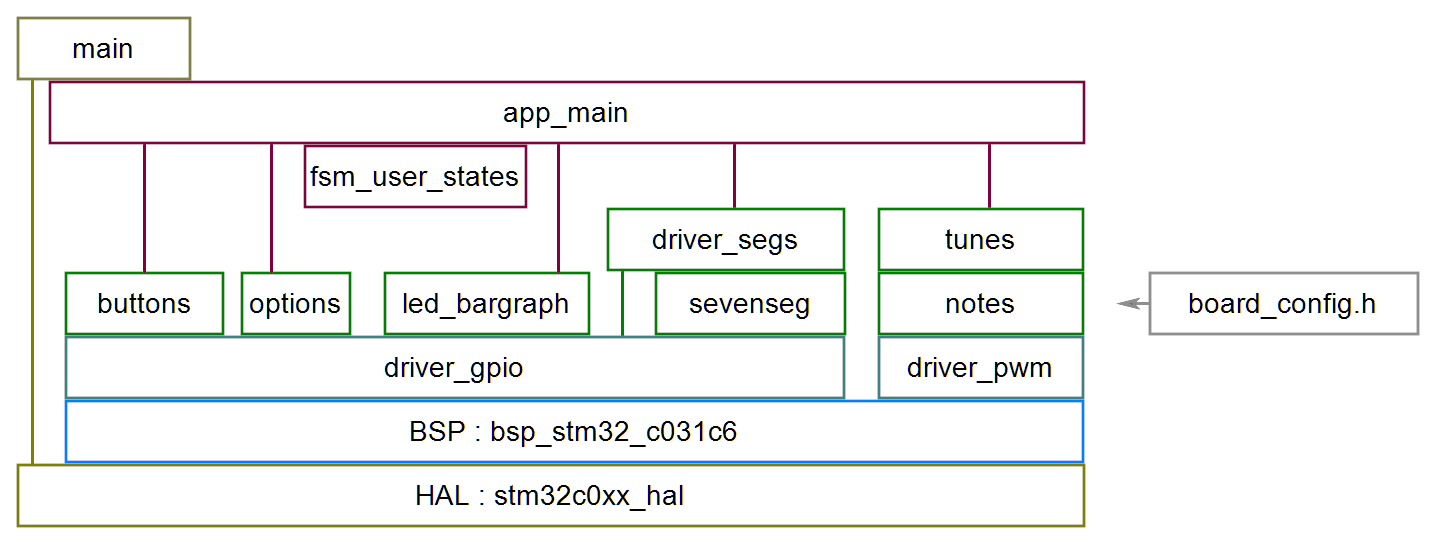
We can't avoid main.c being generated by STM32CubeIDE and directly accessing the HAL, and it's the best place for the Wake pin callback, but we don't have to fall into the trap of putting our application logic in int main(void). Instead, we just call app_init() in the user code initialisation section, and app_run() in the while(1) loop, and let the app_main.c module handle the application layer. This structure allows it to be tested on the host without hardware problems getting in the way.
board_config defines all the IO pins and peripheral register mappings so that the middle layers (shown in in green) can remain hardware independent and reusable.
But we don't use the justification that because main.c has auto-generated HAL calls, we are allowed to make HAL calls anywhere in driver code. The BSP layer is the correct place for all user code HAL calls, with appropriate values being passed through the driver layers.
Seven Segment Displays
The segment drive lines and digit select lines use GPIOs, which abstract the hardware using driver_gpio_state_t structures containing the relevant config structure. This means that driver_segs.c is on top of driver_gpio.h and neither contain any HAL calls, with those being localised in bsp_stm32_c031c6.c.
Within driver_segs.c the segment drive is logical true or false, with any active_high or active_low conversion being configured using a config variable in the config structure and implemented in the driver_gpio_write function.
struct driver_gpio_config_t
{
    void *pport_impl;
    uint16_t pin;
    bool active_high;
    bool is_output;
};
The digits share the segment drives, so only one digit is driven at a time while the others are off using multiplexing as is commonly used to solve the problem of not having enough IO pins for each LED to have it's own. Any rate faster than the persistence of vision could be used, but the faster the better to avoid stroboscopic effects and I had a 1ms timer running for other purposes.
Converting a time in minutes and seconds to a set of segment values is done in seven_seg.c in multiple stages. The countdown timer runs in total seconds, for example if the 1 minute button was pressed the value is 60. It's easy to convert this to minutes and seconds with two digits for each, and account for the option of showing leading zeros. Once we have these four digits in the range 0-9, the conversion to a bitwise value which represents which segments are lit is done using a look-up table. The look-up table was generated by my C# program, which makes it easy to design the characters. I've chosen to use the standard designs instead of the alternatives listed by Wikipedia.
Speaker Driver, Notes and Tunes
Notes
We are assaulted every day by beeping from devices which have been implemented without regard to musical considerations where the engineer randomly chooses 1 kHz, or some multiple of the micro clock since that's easy or the resonant frequency of the sounder for maximum volume. Without turning this device into a musical instrument, I wanted to have some consideration for the pitches of the beeps and make something that could sound nicely harmonic in place of our daily discordant noise. My main concern was to use the correct ratios between the pitches rather than absolute pitch, since the board design didn't use a crystal oscillator for the main clock and is instead relying on the internal HSI 48 MHz oscillator which is specified to have a 1% tolerance.
Clock circuits usually have a 32kHz crystal for long term stability as well as being trimmed for initial accuracy, but since this is designed to run for at most 15 minutes, an error of less than 1% would not be noticed by an end-user unless they take out a stopwatch to check against.
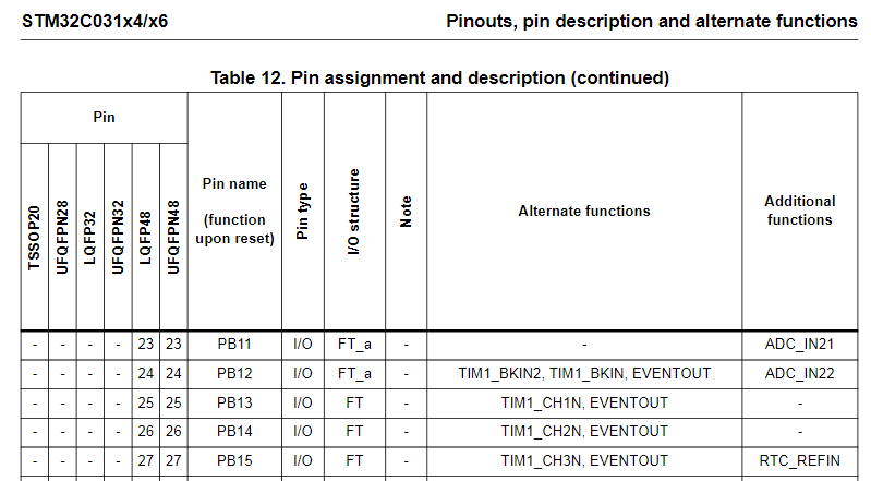
The speaker was wired to PB15, which we can see from Table 12 can be used as TIM1_CH3N.
Setting up PWM on CH3N for Timer 1 is done in the Pinout and Configuration tab of the ioc, and the Parameter Settings tab to set the Mode and polarity
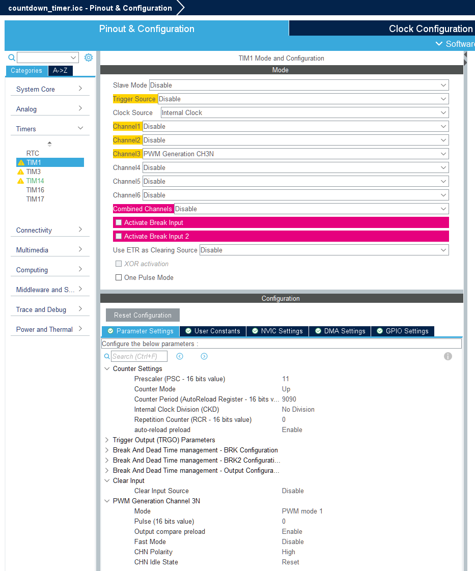
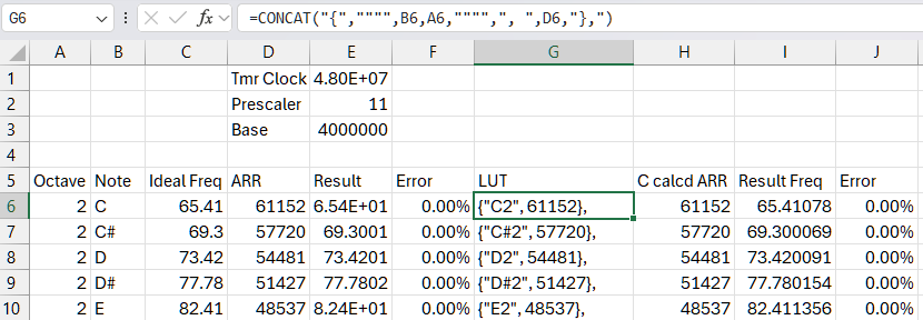
With an input clock to the timer modules of 48 MHz set in the Clock Configuration tab, I calculated the prescaler and auto reload registers according to a spreadsheet set up for the tones I wanted to produce. Using this list of frequencies against notes the frequencies were entered for the notes from C2 (65.41 Hz) to B2 (123.47 Hz) which, with a timer clock of 48.000 MHz and a prescaler of 11, produces ARR values which can be scaled up to octave 7 whilst keeping the frequency error below 0.1%. This covers the majority of the musically interesting scale. Notes outside this range wouldn't be reproduced well by a cheap and tiny speaker anyway. A final column was used to produce the lookup table in a format which can be used in the C code.
Speaker Driver
It's not immediately apparent how to set TIM1->CCER for CC3NE to be set using HAL calls since the only reference to TIM_CCER_CC3NE in the HAL is in TIM_OC3_SetConfig where it is cleared. There is a TIM_CCxChannelCmd function which allows bits in TIMx->CCER to be set but it does not allow for negative polarity channels. So to turn on the PWM output, we need to use register manipulation with the appropriate bit mask, which can be done like this
TIM1->CCER |= TIM_CCER_CC3NE; //PWM On
However, to avoid being dependent on these peripheral register names at the application layer, I've abstracted these out to board_config.h :
static const struct driver_pwm_config_t speaker_pwm_config =
{
    .ptmr_impl = (void *) TIM1,
    .reg_period = (void *) &TIM1->ARR,
    .reg_duty = (void *) &TIM1->CCR3,
    .reg_on = (void *) &TIM1->CCER,
    .mask_on = TIM_CCER_CC3NE,
};
which means that even in the BSP layer we can write general, non hardware specific code :
bool driver_pwm_bsp_set_on(void *preg_on, uint32_t mask, bool on)
{
    if (!preg_on || !mask)
        return false;

    if (on)
        *(uint32_t *)preg_on |= mask;
    else
        *(uint32_t *)preg_on &= ~mask;
    return true;
}
Tunes
I've written functions to play notes in notes.c, using this look up table, including the facility to play rests (silences) using a set tempo and variable note lengths, with configurable duty cycle to change the volume. These notes are used in the tunes when the timer completes and also as button clicks, with separate mute options for clicks and tunes.
For the completion tunes, I didn't want to have anything too long or distinctive so that it doesn't get as annoying as a badly chosen doorbell or phone ringtone. To keep things simple and short I've opted for some major and minor ascending arpeggios, chosen by experimentally playing major and minor scales. It's very easy to change these in the code since it looks like this:
static const note_t tune1[] =   //F Maj 1st inversion ascending, https://muted.io/f-major-chord/
{
    {.length = 2, .pitch.name = "A4"},
    {.length = 2, .pitch.name = "C5"},
    {.length = 4, .pitch.name = "F5"},
};
Similarly, I've just used notes in the C major scale for the button clicks, with Cancel being an octave below the lowest one for the 10 S button.
The option DIP switches are only read when a timing period is started. I don't expect them to be changed on the fly because the DIP switch is inaccessible once the box is assembled; they were only provided to avoid having to attach a programming device to make the sort of small changes that a user might foreseeably request.
Sleep and Wake
Since the design is for a screwed together unit with an internal battery pack, we need it to be capable of lasting a few months of not being used without flattening the battery. After initial power up and after completing a run, the processor is set into STOP mode which consumes less than 0.5mA current. All the LEDs are turned off, the option pullup is pulled low when not reading the switches and the regulator is a low quiescent current type, drawing less than 60uA.
Any button other than Cancel causes the Wake line to go low via diodes which starts the processor so that it can read which button was pressed and start a run. In this state, it can draw up to 400mA depending on how many LEDs are on, but most of the current is drawn from 5V to avoid heating up the 3.3V regulator.
Not all battery packs are suitable because some cut off their outputs at low currents, causing the board not to wake up on a button press.
Display at completion
When the timer completes, the selected tune plays and the LEDs run a spinner pattern that requires a different drive function than for displaying numerals. Each segment around the perimeter of each digit is lit in turn using a bit shift operator and the bargraph runs one LED at a time in quick succession, to draw attention to the completion event.
Running these three actions in parallel does not require an RTOS since the work can be done cooperatively using non-blocking functions and finite state machines which will be covered in the next post.