
Using Finite State Machines to Implement Modal Applications
The ability to trace requirements through to implementation is an important property of commercial software development. As we know from the last 24 years of Agile, it's very rare to be able to obtain a complete, consistent and correct set of requirements at the start of the project, in practice they have to be continually refined during development.
One of the common failings is to think only in terms of positive requirements - everything the product must do; and to forget the negative requirements - everything the product must not do. Very closely related is the problem arising from only specifying part of the logic, the default or happy path e.g. "when the button is pressed ..." and forgetting to specify the other part e.g. "when the button is released ...". It's not always obvious what the product should do when logical states change back to their default, when conditions revert to normal or when users cancel operations, causing developers to make assumptions and resulting in a major source of bugs.
The requirements always start life as a text document but once these start to become understood by the developers, we can translate them into diagrams.
Diagrams are the best way to see the whole system or subsystem design and all the relationships; text is best for details and non-related factors.
In larger and regulated industries, it is the job of the software architect to translate the requirements text into a design which can be expressed in diagrams, but in smaller organisations this falls to the software engineers. There's nearly always some portion of the system that can be represented in diagrams showing the various states or modes that the system can be in and the transitions between them. In contrast to UML state diagrams which are difficult to understand without the background knowledge of all the symbols used, finite state machine models are easy to understand and explain due to their simplicity.
Koopman calls them statecharts and says that they should be used to represent finite state machines and modal behaviour (see BESS 12.3.3). But they are not good for representing long strings of sequential functions - that is what flowcharts are for.
Code with lots of boolean flags resulting in complex conditional statements, often testing for similar conditions in multiple places is a symptom of poor design, is fragile and results in many bugs. Even with supporting tests, no one wants to change the logic because it is difficult to understand and hard to predict how small code changes will affect all the possible flows.
Statechart designs produce simpler and more maintainable code, with reduced risk of having "stuck" states that can't be exited resulting from unforeseen combinations of booleans.
When you have n booleans, you have 2^n combinations - what proportion of these have you detected and tested?
Symbols and Terminology
- States are represented by ovals, with the name of state inside.
- Transitions between states are shown by arcs which are labelled by the event name.
- There is always an initialisation arc for the first state out of reset.
- Each arc is unidirectional.
- States have unique names within that state machine. We use an
enumto list those states. - The system stays in the current state unless an event which is shown on an arc occurs, in which case it transitions to the next state.
- The state machine is evaluated for transitions on a fixed and frequent basis (don't use the run interval to implement delays).
- There is an implicit transition into reset from any state due to external conditions, but all other transitions are explicit on the diagram.
Code Rules
- Since the current state has to be available to the FSM module and the application layer, it is effectively global but we need to prevent inadvertent changes to it which would invalidate all the guarantees that we get by using this formalism. So the only place that the current state is allowed to be changed is in the FSM
run()function and that is where it is determined if we are entering a new state, staying in the same stateoccupyor exiting the current state, and the appropriate handler is called. - Reading the current state must always be done using the
_current_state_get()function, not directly accessing the variable. - The FSM ensures that the state can only change once per run.
- This implementation can only handle 1 event in it's input queue, so each loop iteration must only generate one event before the next
run()is called. - No blocking delays are allowed. Each loop iteration must execute quickly to keep worst case execution time small and reduce jitter. Large workloads must be split up so that in each iteration only a short subset is executed, using a static variable to keep track. Delays have to implemented using the difference between the last timer count and the current one for some interval timer which can wrap at most once for the longest delay.
Countdown Timer as an Example
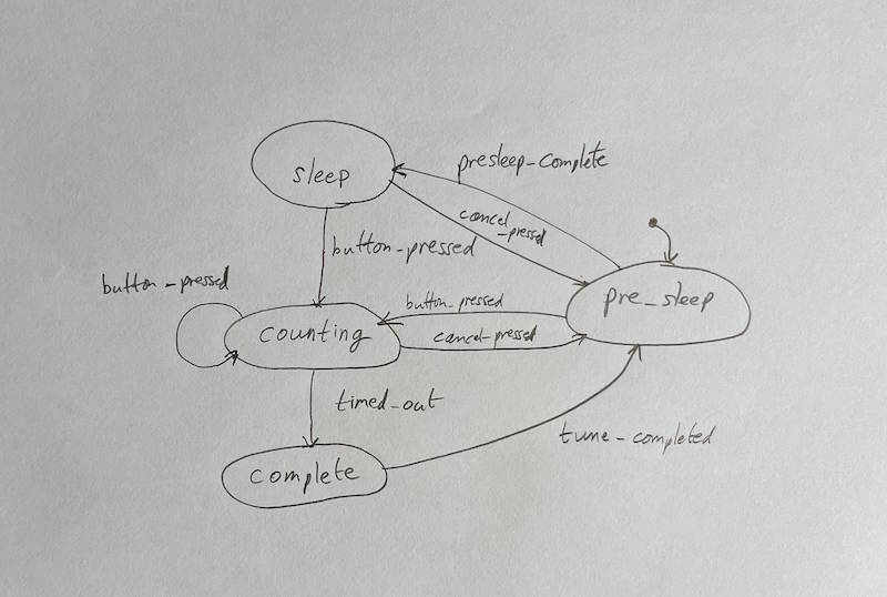
My working method to go from idea to implementation of a finite state machine starts with sketching out the diagram. Start by labelling the discrete states that the system may be in, and add the allowed transitions. Each transition is caused by an event, which is labelled.
Sketching the FSM
The first version is best sketched using pencil and paper, without worrying about being neat. Don't let the tools get in the way of your thinking about the problem at hand. People who like to do all their work on the computer like software engineers often want to do this step in Powerpoint or Visio (I recommended RFFlow instead, lightweight and fast). But paper is best for this stage - use as many sheets as you need for revisions, never lose anything in rework, or by accidentally moving a shape.
Once you've got a design worked out on paper, instead of computerising it using a drawing tool, we can get the computer to draw it for us just by listing the states and the transitions. There's another huge advantage to doing it this way which we will see in later. DOT Language covers the specification of state machines, and we just have to know a few elements of the syntax as illustrated below.
- The first line specifies digraph graph type and sets the namespace of the FSM, used for naming of the files and functions
- Always start with an
uninitstate which is set to invisible. - List the state names, each has a non-optional comment which can contain
entry,occupyand/orexitdepending on which handlers you want to generate. State names are case insensitive. - List of state transitions using the previously defined state names. Each transition is labelled with an event which produces an event enum.
- Double forward slash for rest of line is comment
digraph user_states    // Namespace of the FSM
{
    // List of states with handlers for (entry, occupy, exit)

    uninit [style=invis]                            // Prior to FSM initialisation, nothing useful done in this state
    presleep [comment="entry,occupy"]
    sleep [comment="entry,occupy"]
    counting [comment="occupy"]
    complete [comment="entry,occupy"]

    // List each state transition -> with it's label for the event causing it

    uninit->presleep                                // Always unlabelled
    sleep->counting [label="button_pressed"]
    sleep->presleep [label="cancel_pressed"]
    presleep->sleep[label="presleep_complete"]
    presleep->counting[label="button_pressed"]
    counting->counting [label="button_pressed"]
    counting->presleep [label="cancel_pressed"]
    counting->complete [label="timed_out"]
    complete->presleep [label="tune_completed"]
}
Visualising the FSM using Graphvis
Use either https://magjac.com/graphviz-visual-editor or https://dreampuf.github.io/GraphvizOnline to draw the state diagram in the right hand side pane by pasting the dot file in the left hand pane, and the diagram updates when the dot file is changed.
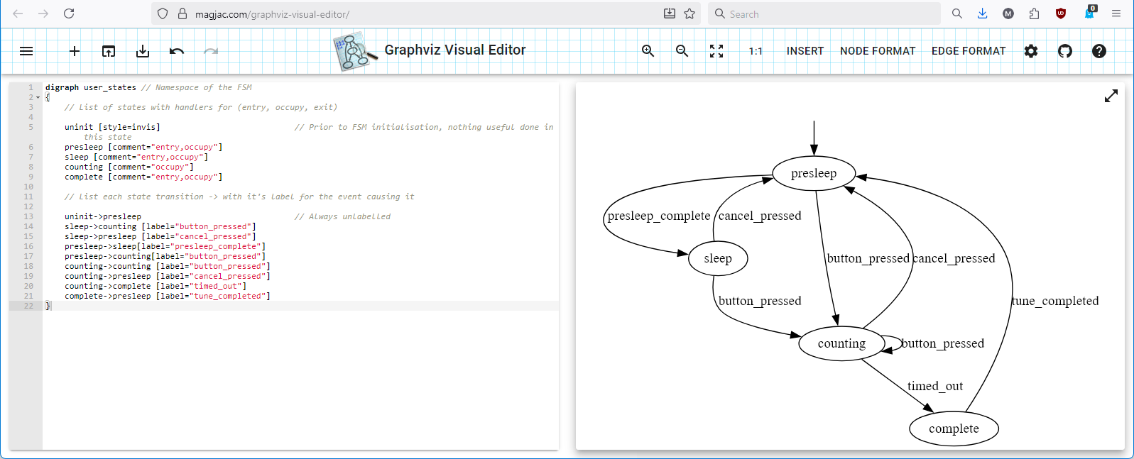
You can't rearrange the ovals with these tools, it is automatically laid out, but that has no effect on the FSM functionality.
State Machine Auto Code Generation
For each dot file in the state_machines folder, the python script fsm_gen.py will convert this into C code. It generates the following files and functionality, leaving you to only add the event handling functions in the app layer. None of these files can or should be hand-edited.
fsm_status.h | fsm_status_enum |
fsm_user_states_impl.h | handler prototypes |
fsm_user_states.c | fsm base functionality |
fsm_user_states.h | events, states enums. states_t and top level function prototypes called by app layer |
Assuming you have python 3 installed and the VS Code python extensions, running fsm_gen.py should be as simple as opening it from the state_machines folder in VS Code and clicking the run button in the top right of the code pane, or Ctrl-Alt-N.
You shouldn't see any errors or other output apart from the generated files, but if you want to see what it is doing or debug it, there is a logging variable on line 18 which can be changed to True.
Having the script generate code results in several advantages. The C code has been tested, is the same across projects and for different state machines within the same project and doesn't need reviewing in each instance. But the biggest advantage is that if the dot file is changed showing an updated diagram, the code will be updated in the same way, just by re-running the script.
It's common to not be sure which handlers you need to generate for each of the states, so you can add them all, and tidy up later by rerunning with the unused ones removed.
Testing that the existing functionality is unchanged is the responsibility of the unit tests which will be covered in a later blog post.
Integrating the FSM into the application
To isolate the FSM code from the application layer variables, we pass in a void pointer to a struct app_state_t containing them during initialisation called context, which is then passed back to the entry, exit and occupy handler functions. In this case, the struct contains the option values, time requested and other timer values which need to be effectively globals. This method also prevents other application functions which don't get passed context from writing to these variables.
Running the FSM requires calling fsm_user_states_run() from the app layer as often as necessary for the state changes to occur, in this case 1 ms. The only other base FSM function that is non-optional is fsm_user_states_event_send() which is passed an event enum when the relevant event occurs, eg USER_STATES_EVENT_BUTTON_PRESSED. The app layer is also responsible for implementing the entry, exit and occupy functions which the FSM engine calls as appropriate. Within these functions, the state is never changed directly but instead they call the event_send() with the relevant event enum.
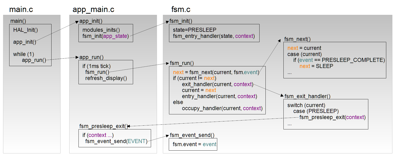
Not all handlers shown to keep the program and data flow clear.
Writing the Entry, Exit and Occupy functions
For those states where the dot file specified that entry, exit or occupy handlers are used, a function will be called by the FSM module with appropriate naming, which runs application layer functionality. For example, the countdown timer's FSM is called user_states, and has a complete state, so there is a void fsm_user_states_complete_entry(void *context) function which plays the tune as determined by the options setting and starts the display spinner.
void fsm_user_states_complete_entry(void *context)
{
  struct app_state_t *papp_state = context;
  play_tune(papp_state->bw_options);
  papp_state->tmr_spinner = 100;  //in 50ms increments
}
Combining state machines with RTOS tasks
This project didn't need an RTOS, but I've previously used this state machine approach for blocks of functionality called subsystems in this post which were contained within one RTOS task, so the technique is proven in production. These "FSMs in subsystems" are lighter and faster than using RTOS tasks, and work well as long as you can break the functionality up into small chunks without any blocking delays or functions.
FSMs are lighter than RTOS tasks
Each RTOS task requires a task context block TCB which is often 512B minimum, on top of the user-specified task variables. You might also need to reserve RAM for queues of data being passed between tasks. If the project doesn't already have an RTOS implemented then you should also count the idle task's stack as additional. The FSM only requires it's user-specified variables and a few state variables to maintain contexts.
FSMs are faster than RTOS tasks
Of course the functions execute at the same speed, but the latencies are a lot lower because you are not waiting for the RTOS scheduler to run to pre-empt a lower priority task. You're also not subject to priority inversion problems or having to play with priorities to get acceptable performance. And it's not just the possible waiting before your function can run, it might also be interrupted by another task.
A commercial project I was involved in used FSMs to solve the problems caused by sub-millisecond hard real-time requirements that couldn't be met with the RTOS, so this isn't just a theoretical concern.
However, on the subject of scheduling, I would not advise departing from Koopman's rules in BESS Chapter 14 - Real Time. He also discusses main loop timing in this post: Making Main Loop Scheduling Timing More Deterministic.
Exploring the code
To fully understand the code described above, you need to see it in context of the project which is now published on GitHub.
Checking Against Requirements
The diagram produced by the visualisers listed above can be easily compared to the documented requirements, and since we know that the code matches the diagram, we can say that the FSM is correct. We've avoided a lot of bugs using this technique, and it's easy to change when requirements do. Implementation of the event handlers still needs manual checking which can be covered by unit tests.
Before we can get to unit testing (off-target testing), we have to set up a C compiler and build system that runs on Windows inside Visual Studio Code, so that is the focus of the next post.
Thanks
Thanks to RZ for making the case for FSM code generation and to WT for the first version of the FSM python script.